Objective:
Learn how to create a surface mesh of a gyroid body and tie it to a solid meshApplies to:
- FE Surface Mesh
- Tie Constraints
- Gyroid Body
Procedure:
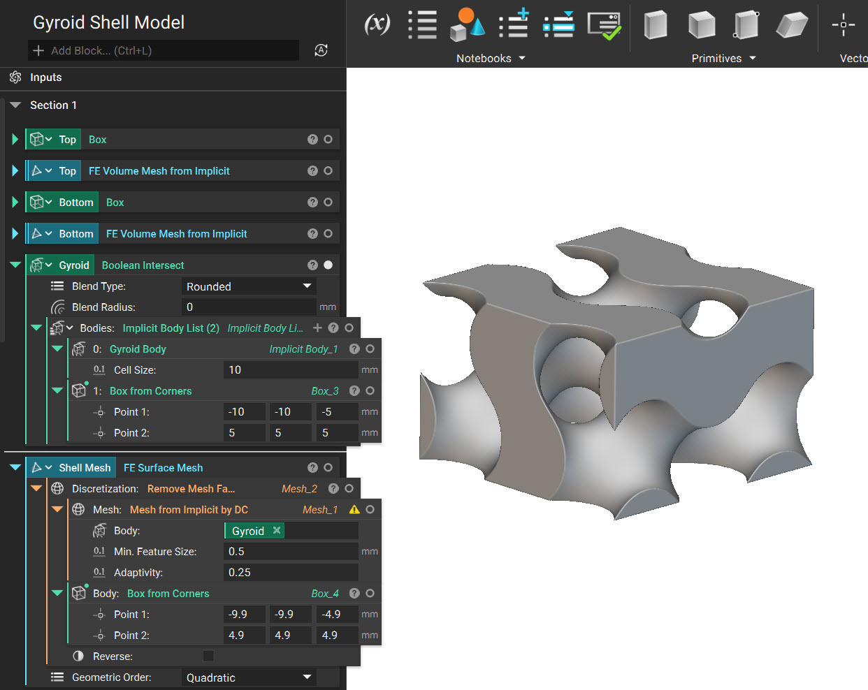
- **Shell a Gyroid Body:**Use the Gyroid Body block with the Set Body Bounding Box. We use the Set Body Bounding Box as the Gyroid Body block creates an infinite field.
Note: Set Body Bounding Box is only used to visualize the infinite field in the defined Bounding Box. You must use a Boolean Intersect block to intersect it to the design space.
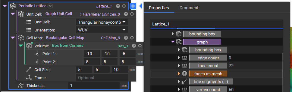
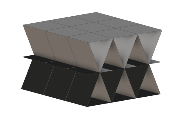
 If you use a Graph Unit Cell, you can use the faces as mesh property to obtain the shell mesh you need.
- Creating a Surface Mesh from the Gyroid Body
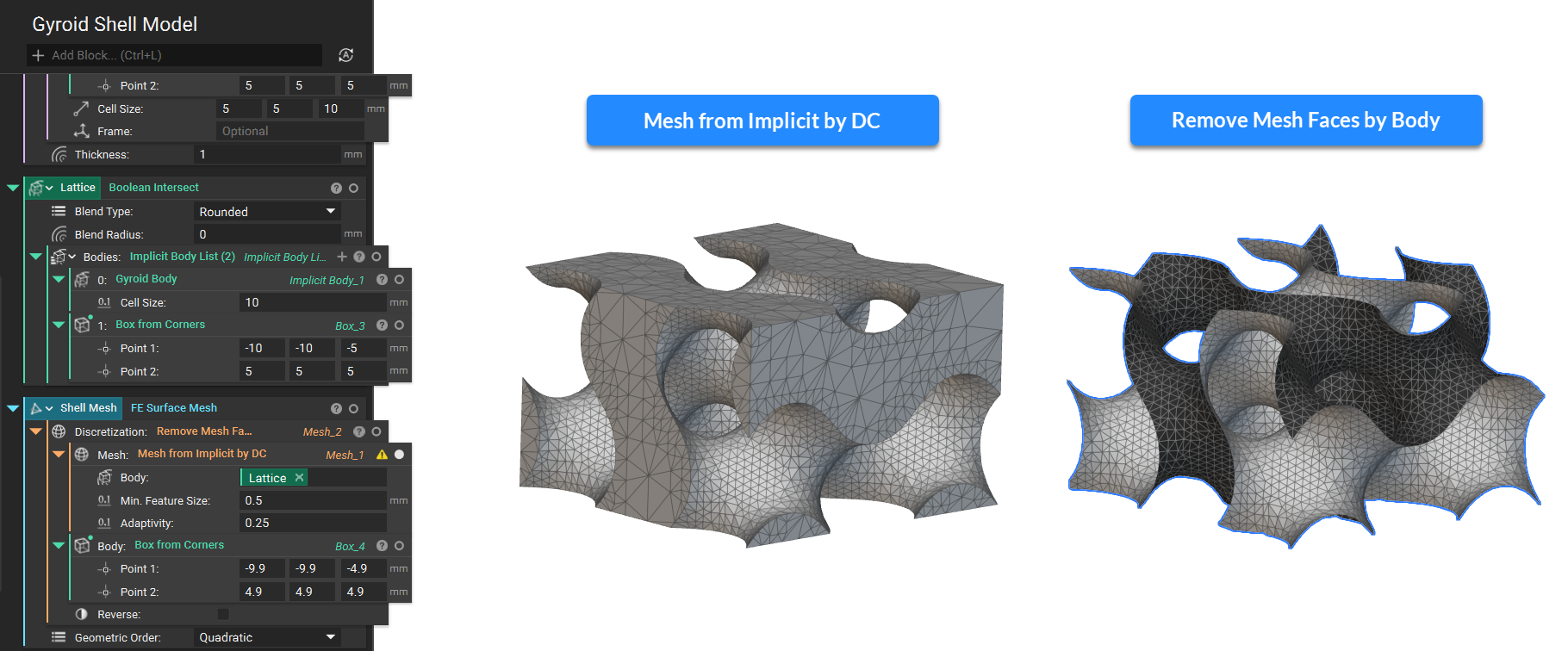 I suggest reviewing this article to learn more about meshing (Methods for creating surface meshes).
3. Creating a Solid Mesh: We create Solid Domains with Solid Attributes for the Top and Bottom Boxes.
I suggest reviewing this article to learn more about meshing (Methods for creating surface meshes).
3. Creating a Solid Mesh: We create Solid Domains with Solid Attributes for the Top and Bottom Boxes.
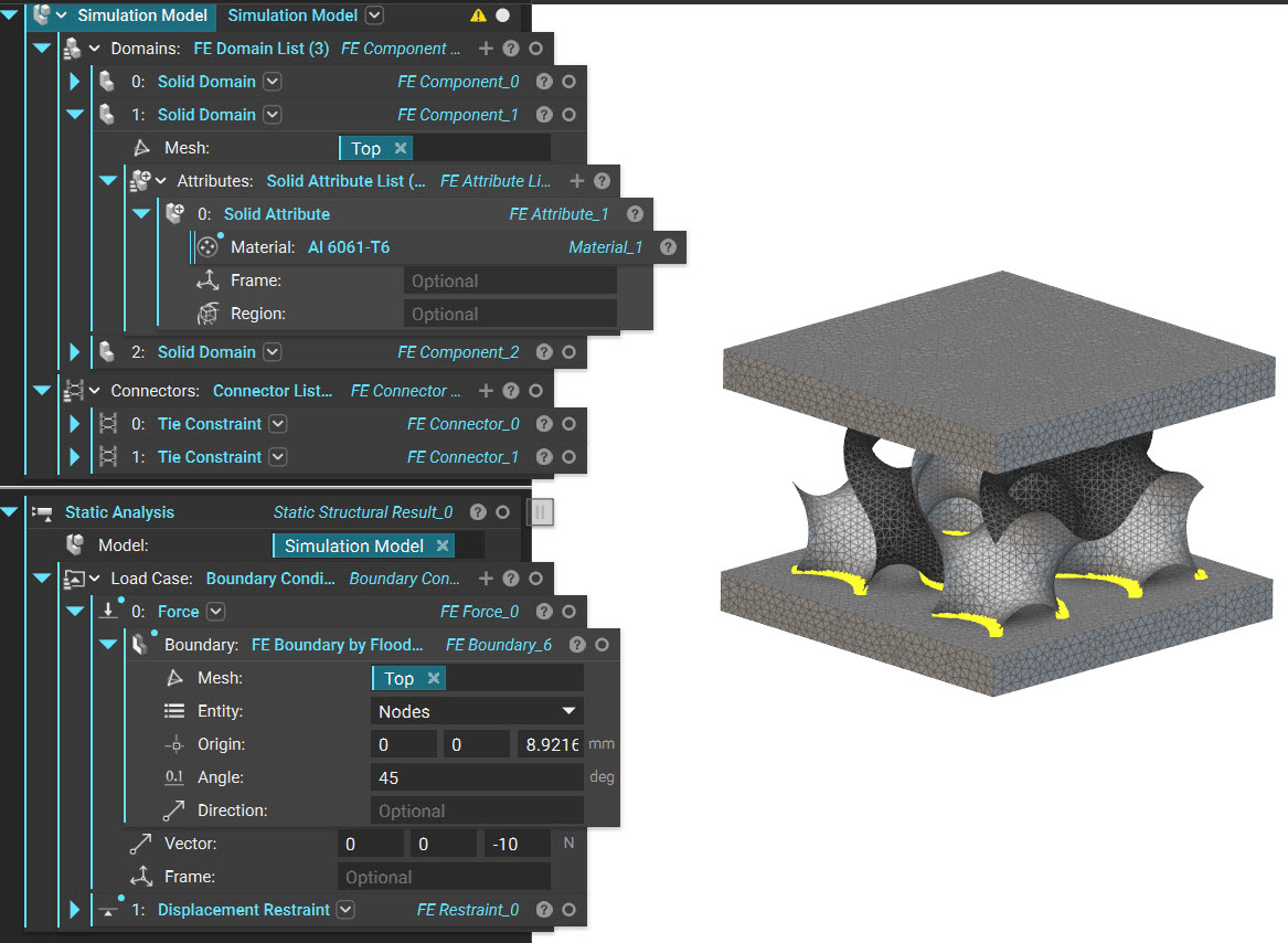
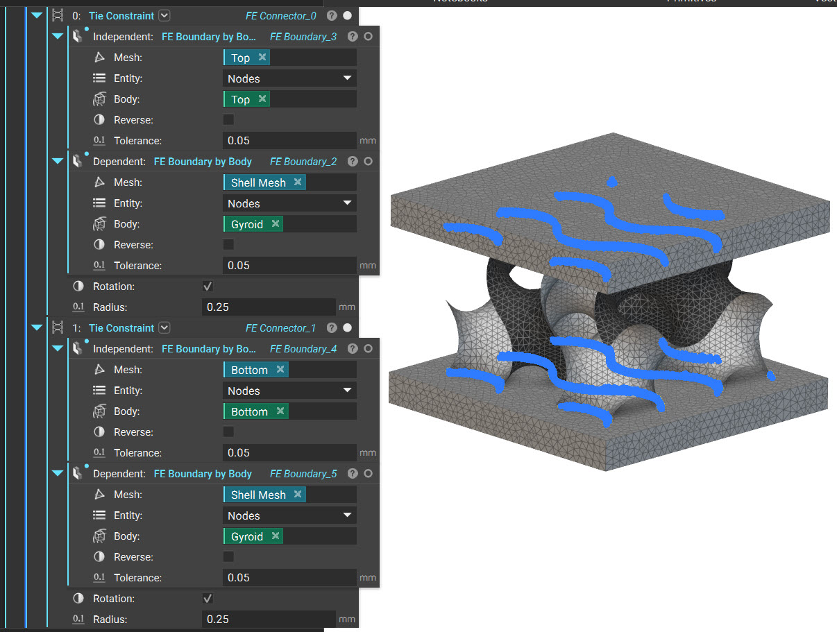
- **Connecting the Surface and Solid Mesh:**Use the Tie constraints to connect the Surface Mesh to the top and bottom bodies.
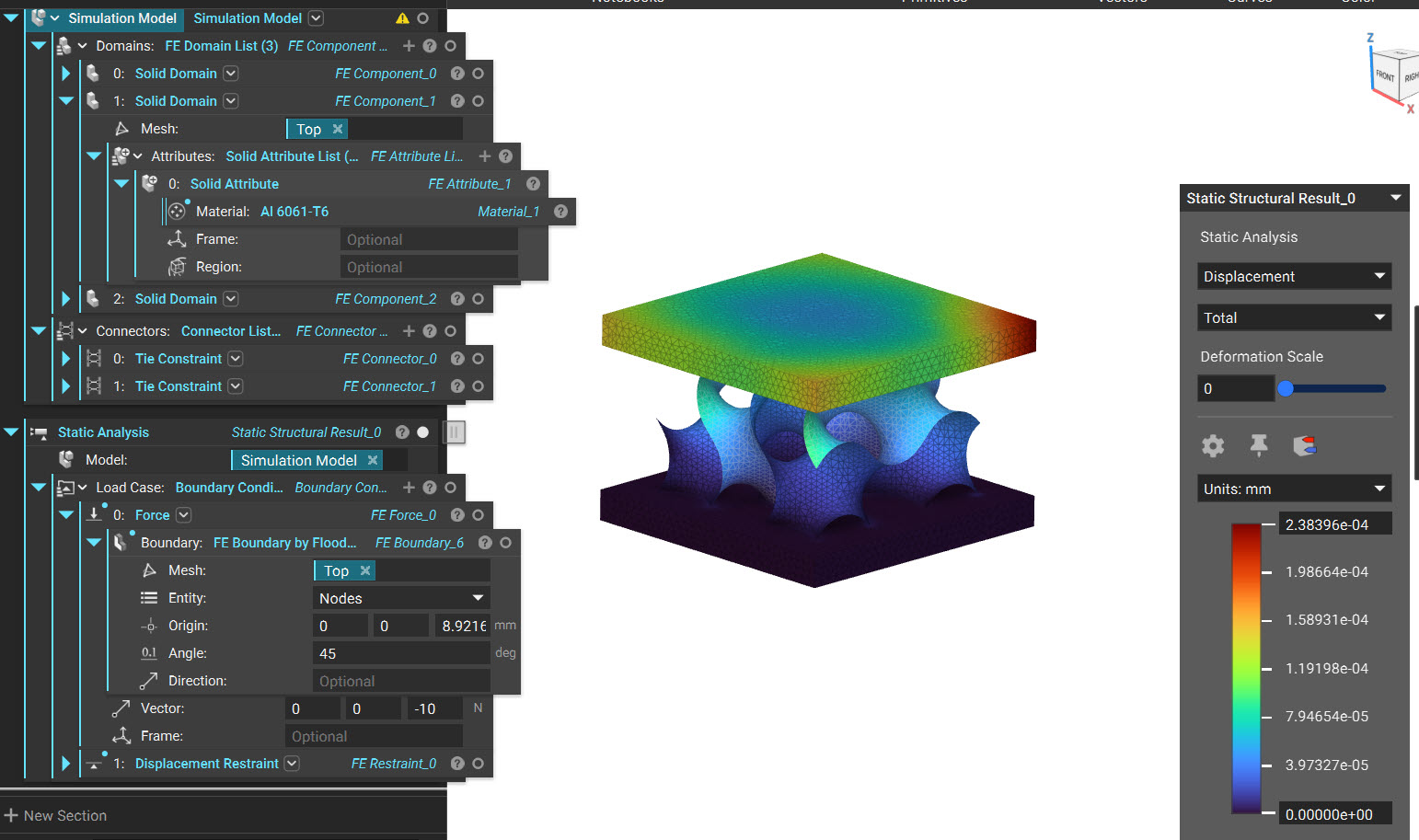 And that’s it! You’ve successfully created a shell mesh of the gyroid body.
Are you still having issues? Contact the support team, and we’ll be happy to help!
And that’s it! You’ve successfully created a shell mesh of the gyroid body.
Are you still having issues? Contact the support team, and we’ll be happy to help!