Objective:
Set up a simulation for a Shell Lattice with a solid body and learn how to use the Shell Attribute.Applies to:
- Cutting down meshing time
- Simulating Shell Lattices
Procedure:
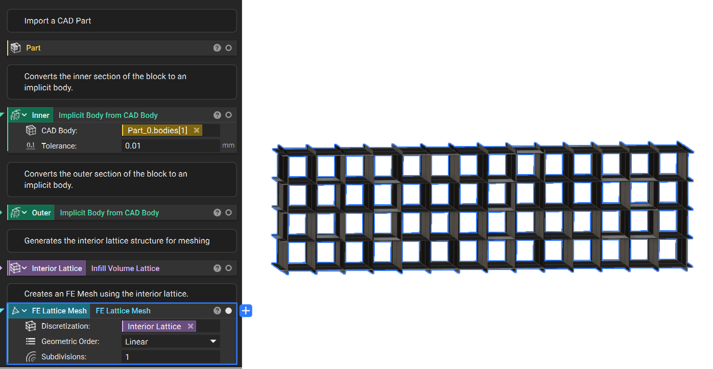
1. Set up: We start with an imported CAD Model:- The CAD bodies have been converted to implicit bodies
- The volume lattice was generated using the inner implicit body region
- Add an FE Lattice Mesh block and input the Interior Lattice.
- Set the Geometric Order to Linear and leave the Subdivisions as 1.
 - - Create an FE Volume Mesh for the outer border.
3. Simulation Domains: The Simulation Model needs a Domain for every mesh.
- - Create an FE Volume Mesh for the outer border.
3. Simulation Domains: The Simulation Model needs a Domain for every mesh.
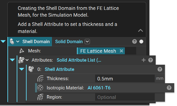
- Create the Shell Domain: Add a Solid Domain.
- Input the FE Lattice Meshfrom Step 2.
- Input a Shell Attribute.
- Set the Thickness and Material.
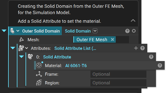
 - - Create the Outer Solid Domain: Add a Solid Domain.
- Input the Outer FE Mesh from Step 2.
- Input a Solid Attribute.
- Set the Material.
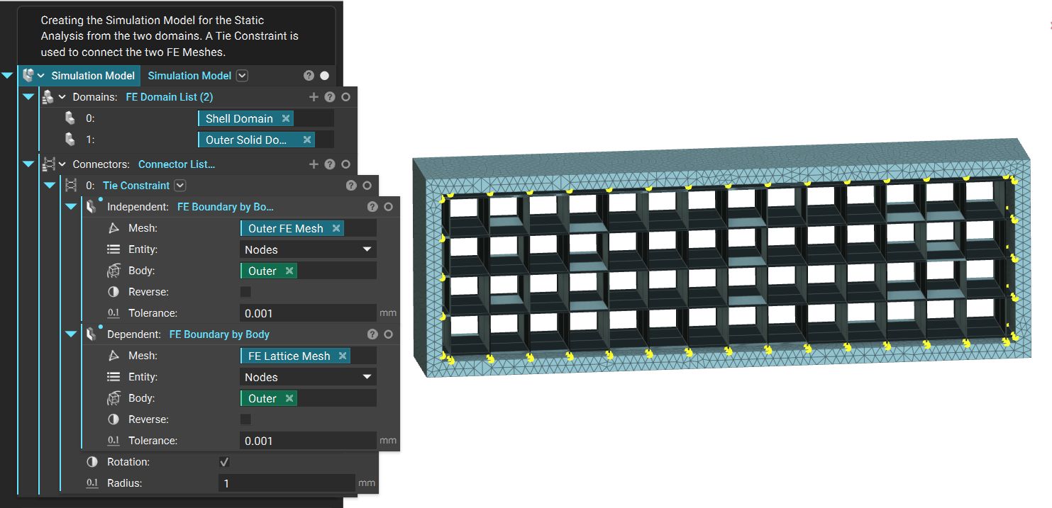
 4. Simulation Model - Tie Constraint: Any Simulation Model with more than one domain needs a Tie Constraint to define how the domains are tied together.
- Add a Tie Constraint block in the Connector input.
- Add an FE Boundary by Body block to the Independent and Dependent Boundary inputs.
- For the Independent Boundary, use the outside border. Use the FE Boundary by Body block to select it.
- For the Dependent Boundary, use the Shell Lattice. Use the FE Boundary by Body block to select where the Shell touches the Outer border.
- Set the Radius on the Tie Constraint to 1mm to allow for the Shell Lattice to be selected.
 The Shell Lattice is now all set up! After step 4, the steps to run the simulation are the same. All you need to do is add Boundary Conditions and run the simulation. Read the articles linked above for more information on those steps.
Are you still having issues? Reach out to the support team, and we’ll be happy to help!
The Shell Lattice is now all set up! After step 4, the steps to run the simulation are the same. All you need to do is add Boundary Conditions and run the simulation. Read the articles linked above for more information on those steps.
Are you still having issues? Reach out to the support team, and we’ll be happy to help!