Objective:
Learn how to use the reaction forces from a previous analysis to run a secondary analysis.Applies to:
- Simulation
- Static Analysis
Procedure:
Before we start, we need to make sure we have completed the static analysis (How to run a static analysis) We can extract the reaction forces from the Static Analysis block Properties panel. The reaction forces property is a Vector Field type, but we want to create a Vector to use in a Force block for our secondary analysis.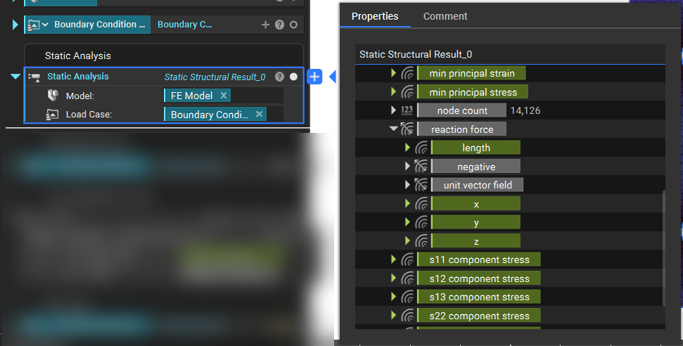
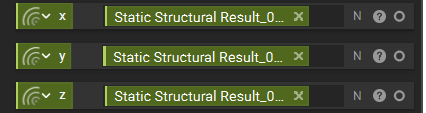
- Extract the X, Y, and Z components from the ‘reaction force’ property chip and add them to the Notebook. Rename them so you know which direction each chip belongs.
- We want to evaluate each of these fields at the nodes they are acting upon. These nodes are found in the Displacement Restraint block used in the earlier Static Analysis Properties panel.
-
- Expand the ‘boundary’ chip and drag the ‘nodes (230)’ chip into the Notebook. Rename the chip to “reaction nodes”
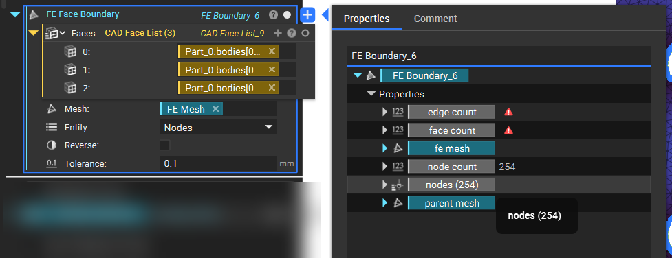
Note: If you used a CAD Face boundary condition, you will not have the boundary chip with nodes. You would have to create a new boundary selection to select the nodes. You can use the FE Face Boundary block to quickly select the nodes.
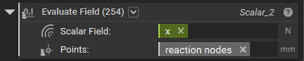
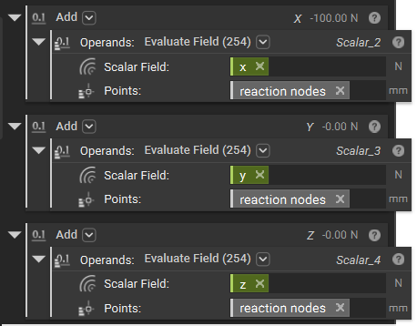
- Once we have the nodes, add an Evaluate Field block for each direction.
- Set the inputs to:
- Scalar field: reaction force x, reaction force y, and reaction force z from Step 1.
- Point: reaction nodes from Step 2.
- Each block has 230 values. We want to add these values to get the reaction force in each direction.
-
- Use an Add block to sum the values together. The result is shown in the right-hand corner of the block (and also in the properties).
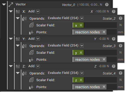
- Use the three values to create a Vector.
-
- Add a Vector block.
- Insert the blocks from the previous step into their respective X, Y, and Z inputs.
- Add a Vector block.
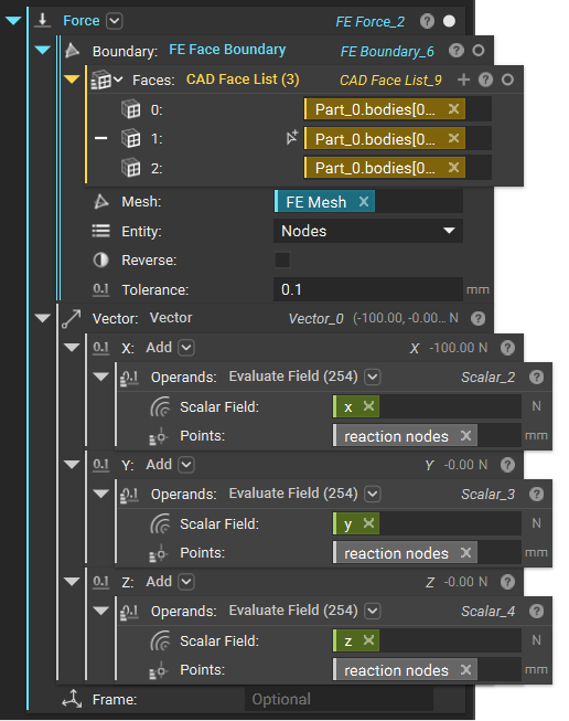
- Build a Force block.
-
- Add a Force block.
- Use the Boundary from the Displacement Restraint in the Boundary input.
- Use the Vector from the previous step in the Vector input.
- Add a Force block.
 And that’s it! You’ve successfully used reaction forces as a boundary condition. If you wish to use the reaction force in Topology Optimization, refer to this article (How to use Reaction Force Response).
Are you still having issues? Contact the support team, and we’ll be happy to help!
And that’s it! You’ve successfully used reaction forces as a boundary condition. If you wish to use the reaction force in Topology Optimization, refer to this article (How to use Reaction Force Response).
Are you still having issues? Contact the support team, and we’ll be happy to help!