Objective:
Learn how to use the Thermal Bonded Contact block.Procedure:
In the figure below, a user would like to tie a copper slug into an aluminum frame. The CAD model on the left represents the geometry of the two materials and the subsequent mesh of the two regions is on the right. Since the FEA meshes of two regions do not necessarily share common nodes and element faces it is necessary to “tie” these two regions together mathematically. As such, this approach allows the user to mathematically “bond” two different objects (of different materials) together and couple them thermally.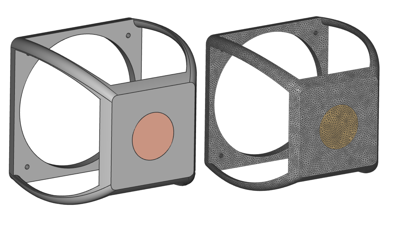 To tie these two materials together the user would use the Thermal Bonded Contact block. This block creates a bonded contact between two FE boundaries which allows for heat flux between the two components.
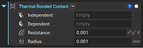
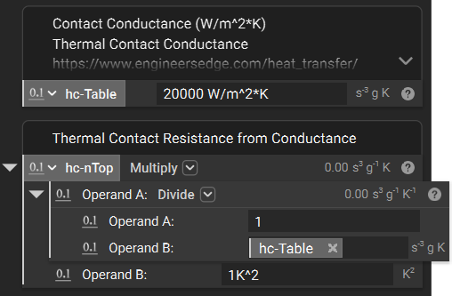
 Contact resistance can be defined to account for thin membrane material at the boundary such as thermal paste. The contact resistance between two materials is often calculated from experimental tests of contact conductance. A table of values is provided below with some common materials.
Table 1: Thermal contact conductance of some metal surfaces (from various sources)
Contact resistance can be defined to account for thin membrane material at the boundary such as thermal paste. The contact resistance between two materials is often calculated from experimental tests of contact conductance. A table of values is provided below with some common materials.
Table 1: Thermal contact conductance of some metal surfaces (from various sources)
| Material | Surface Condition | Roughnessµm | Temperature°C | PressureMPa | hc*W/m2· °C |
|---|---|---|---|---|---|
| Identical Metal Pairs | |||||
| 416 Stainless steel | Ground | 2.54 | 90–200 | 0.3–2.5 | 3800 |
| 304 Stainless steel | Ground | 1.14 | 20 | 4–7 | 1900 |
| Aluminum | Ground | 2.54 | 150 | 1.2–2.5 | 11,400 |
| Copper | Ground | 1.27 | 20 | 1.2–20 | 143,000 |
| Copper | Milled | 3.81 | 20 | 1–5 | 55,500 |
| Copper (vacuum) | Milled | 0.25 | 30 | 0.7–7 | 11,400 |
| Dissimilar Metal Pairs | |||||
| Stainless steel-Aluminum | - | 20–30 | 20 | 1020 | 29003600 |
| Stainless steel-Aluminum | - | 1.0–2.0 | 20 | 1020 | 16,40020,800 |
| Steel Ct-30-Aluminum | Ground | 1.4–2.0 | 20 | 1015–35 | 50,00059,000 |
| Steel Ct-30-Aluminum | Milled | 4.5–7.2 | 20 | 1030 | 4800 8300 |
| Aluminum-Copper | Ground | 1.3–1.4 | 20 | 515 | 42,000 56,000 |
| Aluminum-Copper | Milled | 4.4–4.5 | 20 | 1020–35 | 12,00022,000 |
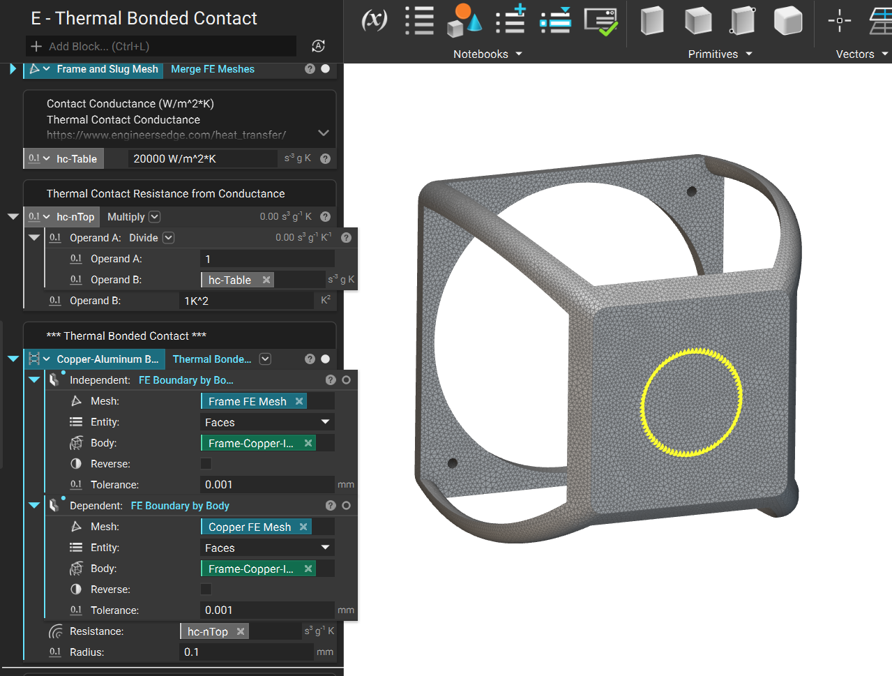
 With the contact resistance properly computed it is necessary to tie the two meshes together as shown in the image below, using the Thermal Bonded Contact block.
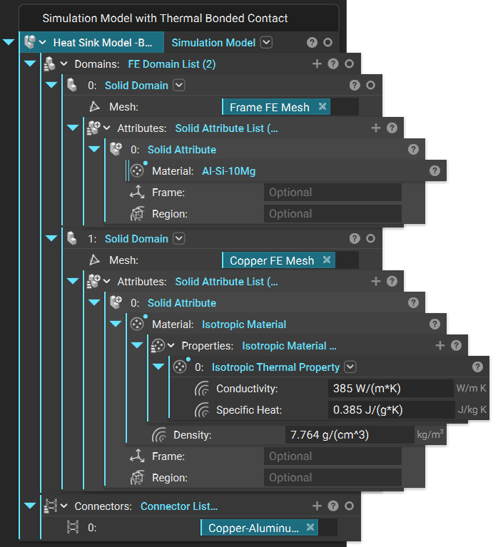
 To properly include Bonded Contact in your FEA analysis you must use include the Thermal Bonded Contact block in the “Connectors” input of your Simulation Model as shown in the image below.
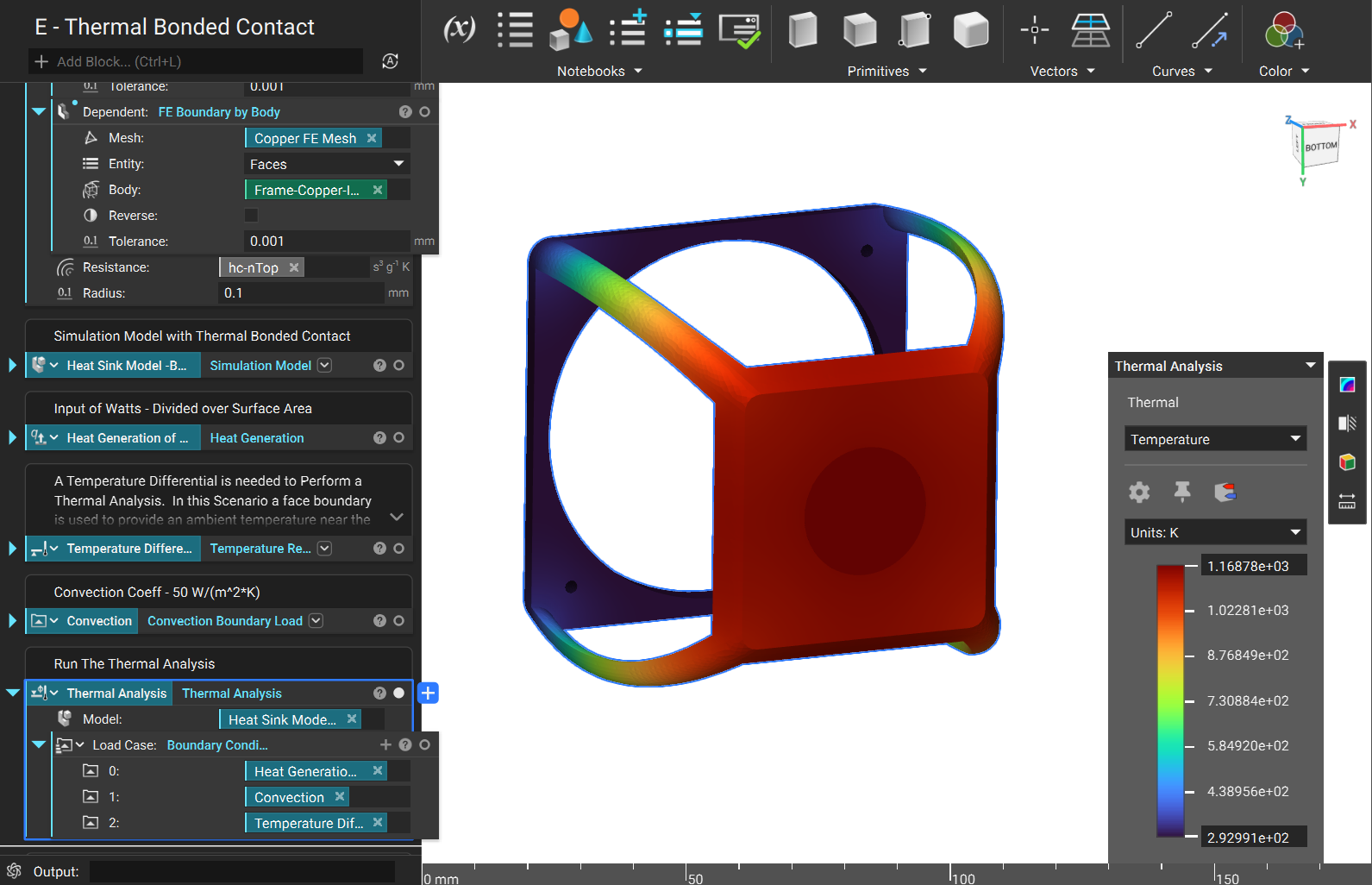
 Once your thermal boundary conditions are input you can now run your thermal analysis using bonded contact!
 Are you still having issues? Contact the support team, and we’ll be happy to help!