

Introduction
In the previous lesson, you examined one source of unexpected field behavior. Operations such as Remap Field, as well as geometries such as ellipsoids and TPMS lattices, can produce fields with an accurate zero surface but a gradient magnitude that differs from one. As a result, offsets and blends may not appear at the intended distances. A second category of unexpected behavior arises from interactions between underlying fields rather than from the visible geometry itself. These outcomes, referred to here as implicit artifacts, may appear as unintended walls, unusual surfaces after a loft, or Boolean results that don’t match the geometry displayed in the viewport. An implicit body may look correct but still contain coincident zero surfaces or other field behavior that affects downstream operations. In this lesson, you will create and debug examples of unexpected implicit geometry, identify coincident zero surfaces, use the Field Viewer to trace problems through a Notebook, and recognize when infinite fields provide a more robust modeling approach.Understanding Implicit Artifacts: False Zeros
As discussed in previous lessons, a signed distance field assigns a value to every point in space. Values are negative inside an implicit body, positive outside it, and zero at its boundary. The surface displayed in the viewport represents this zero-value boundary. Modeling operations, including Booleans, offsets, and shells, operate on the underlying field rather than only on the visible surface. In most cases, the result matches the expected geometry. However, unexpected results can occur when the field contains unintended zero values.What is a False Zero?
When two input bodies share the same face, end cap, or edge, their combined field may equal zero at locations that do not represent the intended boundary. nTop calls this condition a false zero. A false zero may not be apparent in the viewport because the rendered body can still appear correct. However, it can affect downstream operations that evaluate the field, producing an unintended wall, closing an expected opening, or causing an offset, shell, Boolean operation, mass-properties calculation, or slicing operation to return unexpected results. These outcomes are called implicit artifacts. Common causes include:- Creating coincident faces, edges, or end caps between bodies
- Allowing bodies to touch without overlapping before a Boolean operation
- Using infinite fields without restricting the region in which they are evaluated
- Defining an unsuitable bounding box for an operation involving an infinite field
Revealing False Zeros – Pipe Example
A simple pipe demonstrates how a field-quality issue can remain hidden until a downstream operation evaluates the underlying field differently.Create the Pipe
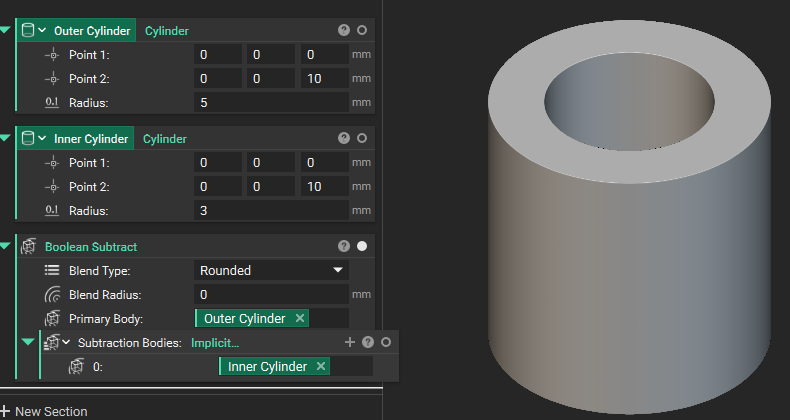
- Add a Cylinder block to create the outer cylinder.
- Add a second Cylinder block with a smaller radius.
- Assign both cylinders the same start and end points. This makes their end caps exactly coincident.
- Use Boolean Subtract to subtract the smaller cylinder from the larger cylinder.
- Display the resulting implicit body.
Expose the Implicit Artifact
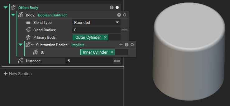
- Add an Offset Body block.
- Drag the created pipe to the block’s Body input.
- Apply a small positive offset. Distance: 0.5 mm
Diagnosing the False Zero with the Field Viewer
As introduced in previous lessons, the Field Viewer provides insight into the underlying field and is an essential tool for diagnosing unexpected implicit geometry.- Return to the output of the Boolean Subtract block.
- Open the Field Viewer for the resulting body.
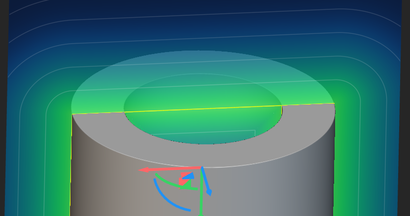
- Toggling Highlight Zero on identifies zero-valued regions, making unintended zero surfaces easier to locate.
- Position the viewing plane near one end of the pipe, where the cylinders’ end caps coincide.
- Inspect the field for zero values that do not correspond to the intended boundary. In this example, a band of false-zero values appears along the end face.
- Identify the region where the unexpected geometry appears.
- Use the Field Viewer to inspect the output immediately before the operation that revealed the issue.
- Examine the underlying field within the affected region.
- If the field appears correct, move one block upstream in the Notebook and inspect its output.
- Continue tracing the workflow backward until you locate the first block that introduces the unexpected field behavior.
Fix the Pipe
The inner cylinder should extend completely through the outer cylinder rather than terminate at the same locations.- Extend the inner cylinder beyond both ends of the outer cylinder.
- Where possible, define this extension parametrically so that the cutting cylinder continues to pass through the outer cylinder as the model dimensions change.
- Repeat the Boolean Subtract operation using the extended cylinder as the cutting body.
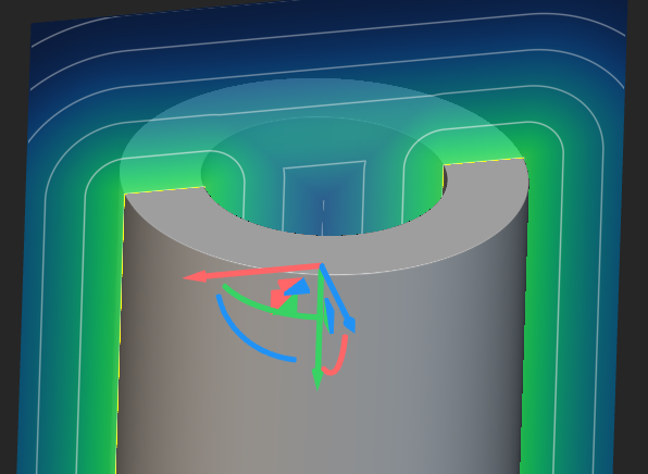
- Inspect the resulting field with the Field Viewer and confirm that the coincident zero surfaces are no longer present.
- Reapply the Offset Body operation.
Coincident Surfaces in Boolean Unions
False zeros are not limited to subtraction operations. They can also occur when two implicit bodies meet at a coincident boundary before a Boolean Union.Create a Coincident Surface
- Add two Cube blocks.
- Position the cubes side by side.
- Align the cubes so one face of each body occupies the same location without overlap.
- Combine the cubes using Boolean Union.
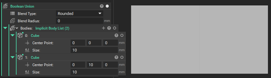
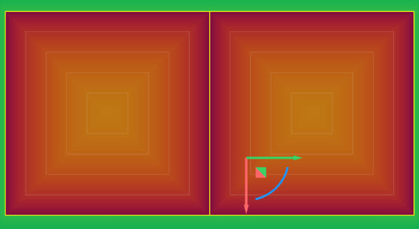
Correct the Union
Unlike the cylinder example, there is no cutting body to extend. Instead, create a deliberate overlap between the two bodies:- Move one cube slightly into the other so that the bodies share a region of volume rather than a single face.
- Inspect the revised result with the Field Viewer.
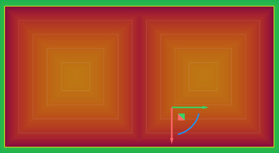
Infinite Fields and When to Use Them
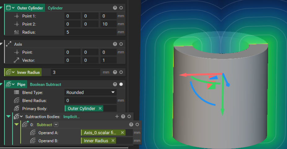
You have already worked with an infinite field: a profile’s Distance to Extrusion property. Because this field has no defined start or end, you need a Set Bounding Box or Boolean Intersect operation before you can use it as finite geometry. The same principle applies to the hollow-cylinder example. If the inner cylinder exists only to create a through-hole, its endpoints are not part of the design intent. A finite cutting cylinder introduces unnecessary end caps that may coincide with the outer cylinder and create false zeros. An infinite cylindrical field eliminates those boundaries entirely.Create an Infinite Cylindrical Field
- Add an Axis block and place it along the outer cylinder’s centerline.
- From the Axis property menu, extract its Scalar Field. This field represents the distance from every point in space to the axis.
- Create a variable for the desired hole radius.
- Add a Subtract block and subtract the radius from the axis-distance field.
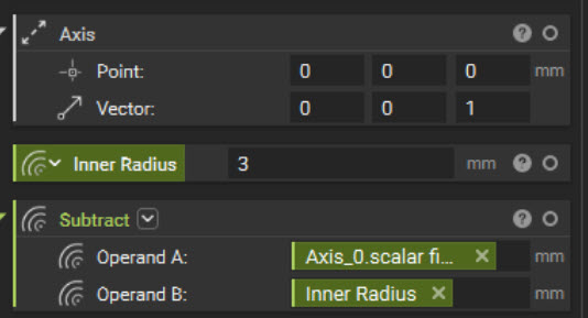
- daxis is the distance from the axis.
- R is the desired hole radius.
- Subtract the infinite cylindrical field from the outer cylinder.
Choosing Between Infinite Fields and Finite Bodies
Use an infinite field when:- A feature must pass completely through a body.
- The feature’s endpoint is not part of the design intent.
- The geometry depends only on distance from an axis or plane.
- A finite cutting body would introduce unnecessary zero surfaces.
- Another body determines the feature’s final extent.
- A blind hole
- A finite cavity
- A pocket with a specified depth
- A feature with explicitly defined endpoints
What to Take Away
- An implicit body can appear correct in the viewport, but its underlying field may contain false zeros that affect downstream operations.
- False zeros can occur when bodies share coincident faces, edges, or end caps. They may appear in both subtraction and union workflows.
- The operation that exposes an implicit artifact isn’t necessarily the one that created it. Use the Field Viewer to trace the field backward through the Notebook and identify where the issue first appears.
- Use infinite fields when endpoints are not part of the design intent. Use finite bodies when a feature requires a defined depth or explicit start and end locations.
- Apply a bounding box or intersection only when an infinite field must be restricted to a finite evaluation region.