

Introduction
The previous lesson, Working with External Data in nTop, focused on bringing external data into nTop and converting it into geometry for modeling. A CSV file became a profile, while mesh and CAD files were converted into implicit bodies. This lesson focuses on the reverse process: preparing nTop geometry for use in downstream tools or FEA in nTop. An Implicit Body is nTop’s native geometry representation. While the number of tools that can work directly with implicit geometry through Implicit Interop, introduced earlier in this learning pathway, continues to grow, many downstream applications still require other formats, such as mesh or CAD files. In this lesson, you will learn how to prepare and export geometry from nTop. You will begin by meshing an implicit body, then explore four export paths: mesh, CAD, curves, and implicit geometry. Along the way, you will examine each approach’s strengths and limitations as geometric complexity increases.Note: This lesson focuses on surface meshing techniques, which capture the geometry’s boundary. For volumetric meshing techniques, refer to the FE and Volume Meshes section of the Intro to Meshing course.
Meshing in nTop
Meshing discretizes a 3D model into a collection of smaller elements that approximate its geometry. Increasing the number and refinement of these elements generally produces a closer approximation of the original geometry. There are three primary mesh types used in nTop:- Mesh (Surface Mesh): Represents the boundary of a 3D body using two-dimensional elements.
- Tetrahedral (Tet)/Volume Mesh: Discretizes a body’s interior volume using three-dimensional elements.
- Finite Element (FE) Mesh : A solid mesh prepared for use in finite element (FE) simulation. nTop supports linear and quadratic elements.
Note: nTop’s Finite Element Analysis (FEA) does not support a quad mesh; these meshes in nTop are used to create a NURBed body
- Mesh geometry defines each vertex’s position and geometric characteristics.
- Mesh connectivity defines the relationships between mesh elements, such as which vertices and edges form a face and which elements are adjacent.
Mesh Properties and Terminology
Four fundamental mesh properties assess mesh quality: closed, manifold, oriented, and self-intersecting. These Boolean properties appear as True or False in the Properties section of the block details and indicate whether a mesh is clean and suitable for downstream use. Additional mesh-specific properties, including face count, vertex count, and vertices, are also available for inspecting the mesh geometry.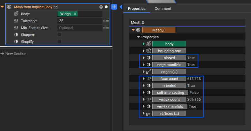

Edges and Closed Meshes
Edges and Closed Meshes
A mesh can be classified by its edges, which help determine whether the mesh is closed. A closed mesh has no boundary edges; every edge is shared by at least two faces.Mesh edges are classified into three types: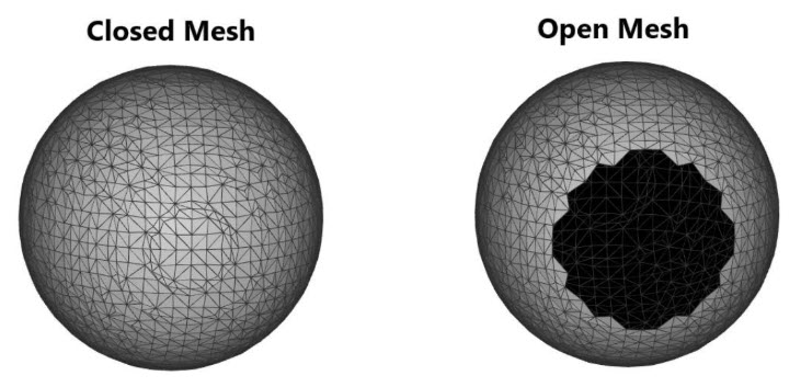 An example of a closed mesh (left) vs an open mesh (right)
- Boundary Edge: Adjacent to exactly one face. A boundary edge indicates that the mesh is not closed.
- Regular Edge: Adjacent to exactly two faces.
- Singular Edge: Adjacent to more than two faces.
Manifold Meshes
Manifold Meshes
For a mesh to be manifold, it must form a continuous surface that locally resembles Euclidean space. One way to think about this is: “If I could shrink myself down, could I walk across the entire mesh without encountering an invalid connection or discontinuity?”The causes of a non-manifold mesh are not always immediately apparent. The following are some common scenarios that can result in non-manifold geometry: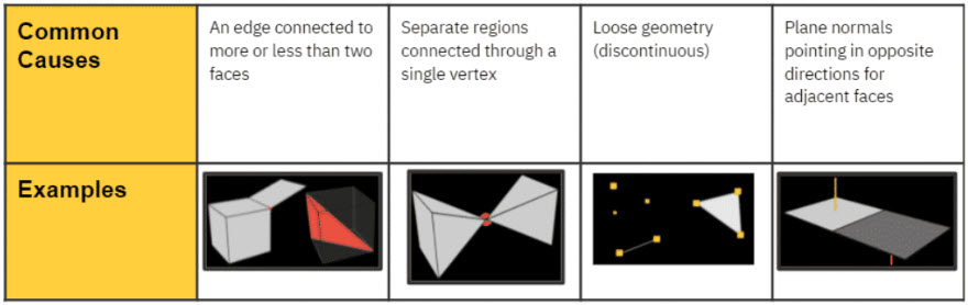 Several examples of non-manifold mesh geometry
Oriented Meshes
Oriented Meshes
Orientation provides a consistent way to distinguish between the two sides of a mesh face.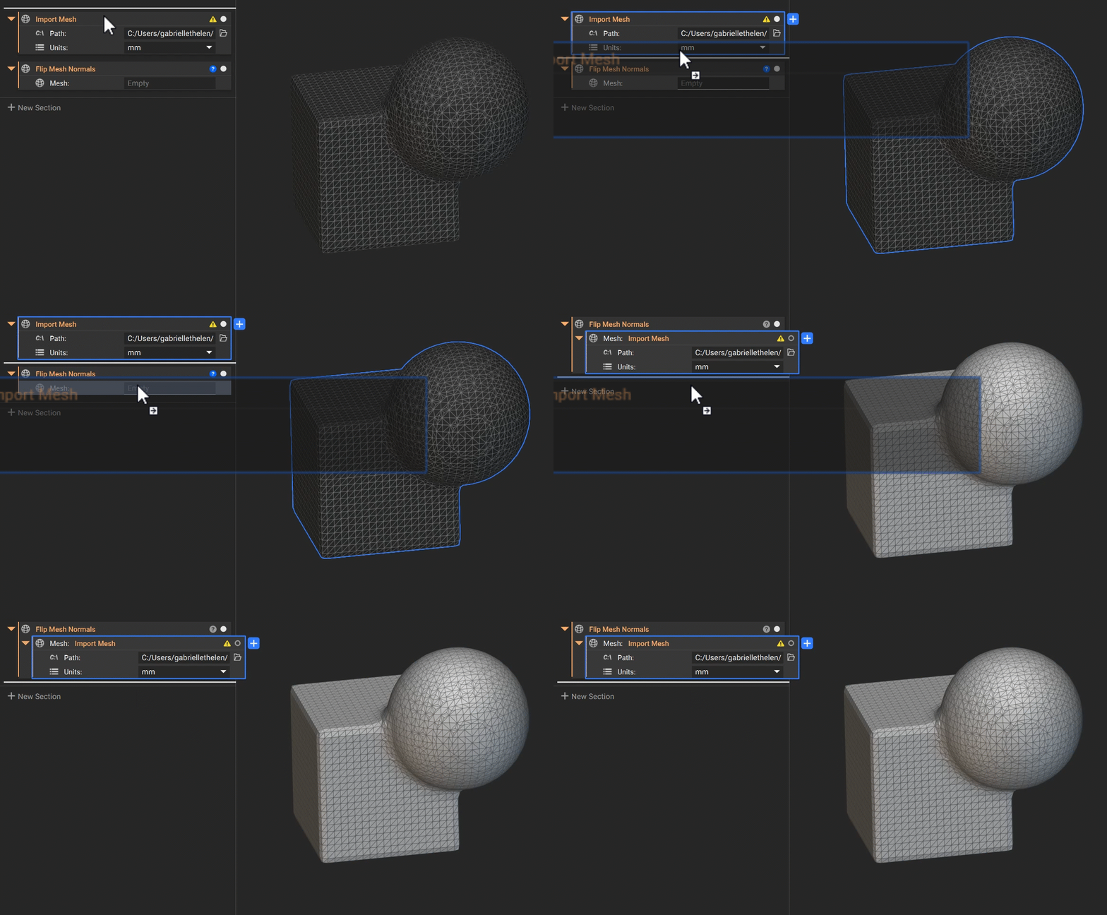 Use the Flip Mesh Normals block to reverse the normal direction of the mesh elements
- An oriented mesh has face normals that consistently point in the same direction—either outward or inward.
- Face orientation determines which side is the top (outward-facing, shown in gray) and which is the bottom (inward-facing, shown in black).
Self-Intersecting Meshes
Self-Intersecting Meshes
A self-intersection occurs when one part of a surface mesh intersects another part of the same mesh, causing two or more mesh elements to overlap or cross.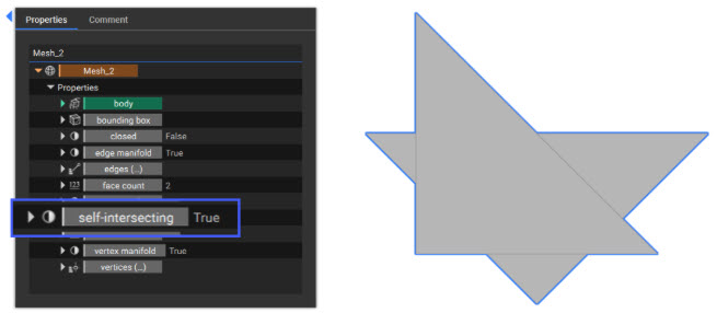 A self-intersecting mesh will have the corresponding property set to “True”
Meshing an Implicit Body
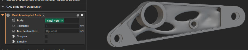
The Mesh from Implicit Body block, found in the Utilities tab under Conversion, converts an implicit body to a mesh.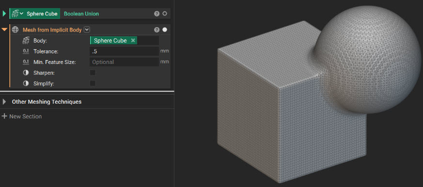
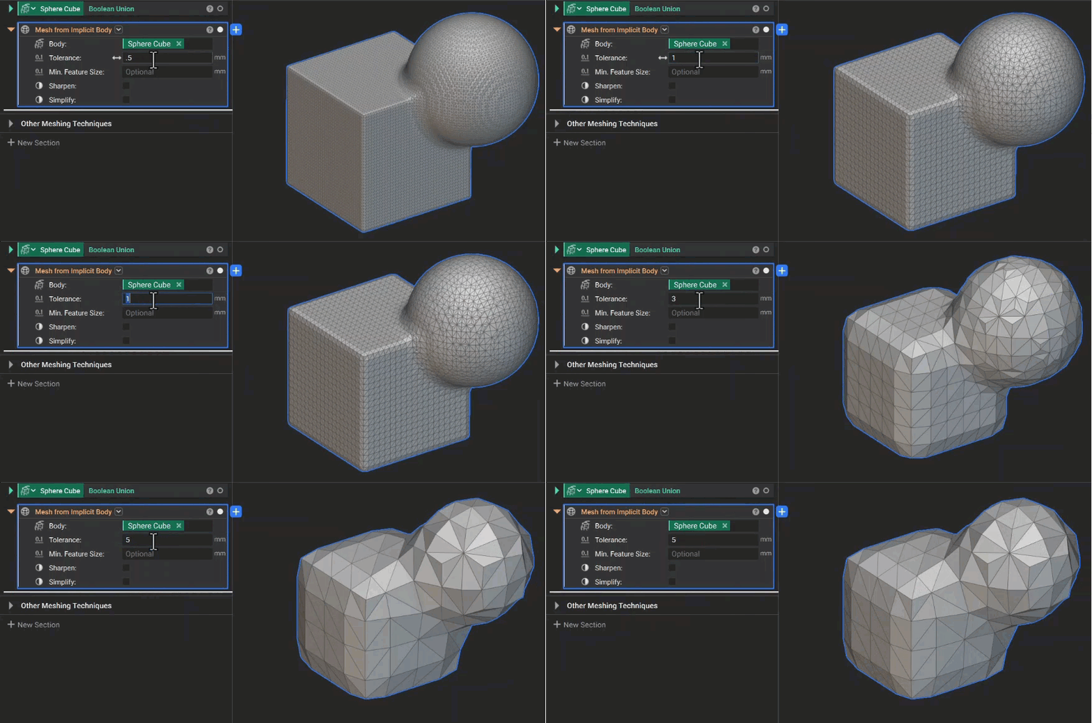
- Tolerance: Defines the maximum allowable deviation between the mesh and the implicit surface. Within the block, the tolerance determines the voxel size, which is set to half the specified tolerance. A voxel is a small, three-dimensional cell used to sample and represent the geometry during the meshing process. Smaller voxels capture finer geometric detail but require more mesh elements. As a result, halving the tolerance can approximately quadruple the triangle count.
Note: A useful starting point is to set the tolerance to approximately half the thickness of the smallest feature you want to preserve.
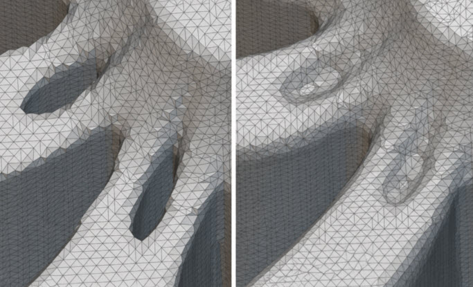
- Min. feature size: An optional input that filters out features or holes smaller than the specified value. Use this input when the resulting mesh captures small geometric details that are unnecessary or below the limits of the intended downstream process.
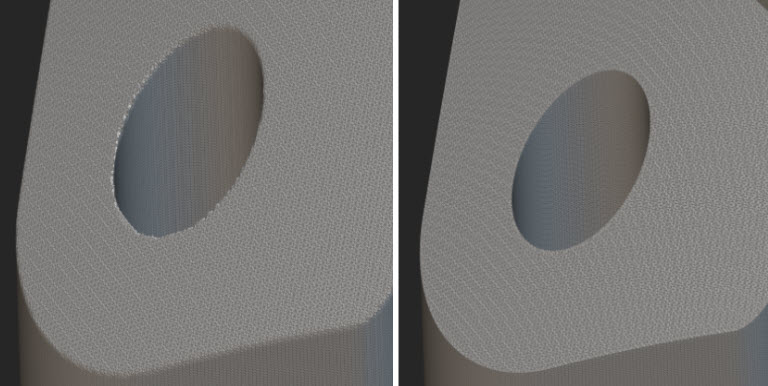
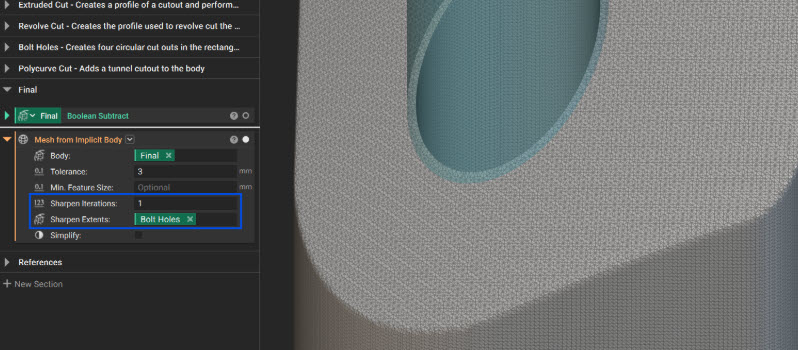
- Sharpen: Reconstructs sharp edges and corners that may become rounded during voxelization. Enabling this option approximately doubles computation time.
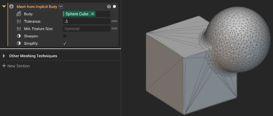
- Simplify: Reduces the number of mesh elements while maintaining the specified input tolerance. When enabled, it aggressively decimates and combines about 90% of the mesh elements, which can significantly reduce mesh size but may reduce geometric fidelity or introduce defects, such as self-intersections.
- Simplify Mesh by Amount reduces an input mesh’s face count by removing a specified proportion of its triangles. The Amount input must be greater than 0 and less than 1. For example, an input of 0.5 reduces the mesh face count by 50%.
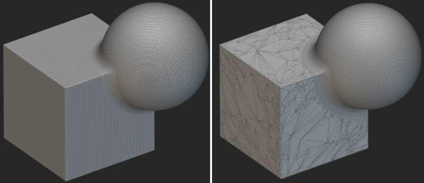
Note: The simplification algorithm does not account for surface tolerance, which defines the maximum allowable distance between the original and simplified mesh surfaces. To maintain a specified surface tolerance during simplification, use the Simplify Mesh by Threshold block.
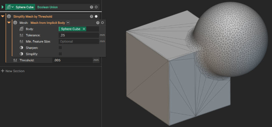
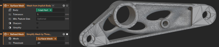
- Simplify Mesh by Threshold removes as many mesh elements as possible while keeping the surface deviation between the input mesh and the simplified result below a specified threshold. Think of the Threshold input as Chord Height. This approach is useful for geometry that combines large, simple regions with fine features because it prioritizes geometric fidelity over achieving a fixed reduction percentage.
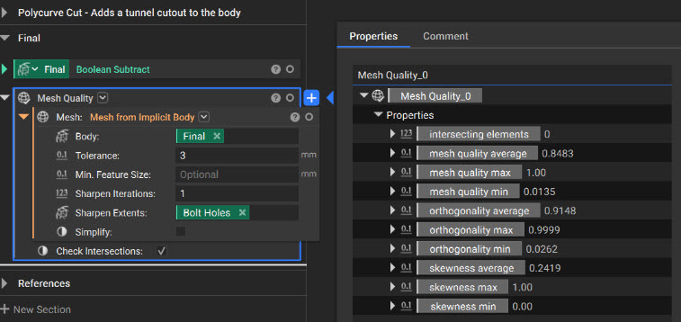
- Skewness measures how much an element deviates from its ideal shape. Values range from 0 to 1, with values closer to 0 indicating higher-quality elements and values closer to 1 indicating highly distorted or potentially degenerate elements.
- Orthogonality measures how closely an element conforms to an ideal orthogonal arrangement. Values range from 0 to 1, with values closer to 1 indicating better-quality elements and values closer to 0 indicating greater distortion.
- Intersecting triangles identify triangles that overlap or pass through one another. Ideally, no triangles should intersect.
Remeshing
The Remesh Surface block improves mesh quality by redistributing elements across an existing surface mesh. It can reduce element count, improve element size and shape consistency, and vary mesh density spatially. Use this block to prepare high-quality surface meshes for downstream applications such as finite element analysis.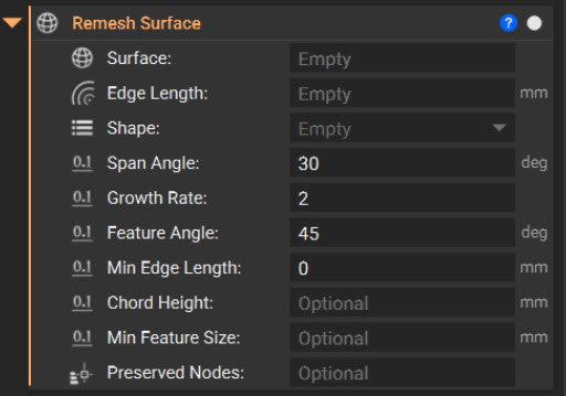
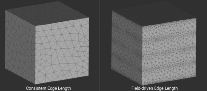
- Edge Length: Specifies the approximate edge length of the mesh elements. It can be a constant value for uniform sizing or a scalar field to vary mesh density across the surface.
- Shape: defines the element shape of the output mesh. Triangular elements are the most common and computationally efficient option. Although quad and quad-dominant surface meshes cannot be converted directly into volume meshes in nTop, you can use them as inputs to the CAD Body from Quad Mesh block, which is discussed later in this lesson.
- Span Angle: controls refinement along curved regions by defining the maximum angle that a mesh element may span across a curve. Smaller values produce greater refinement, allowing the mesh to represent curved geometry more accurately. The following ranges provide general starting points:
- Coarse: 60°–91°
- Medium: 24°–75°
- Fine: 12°–36°
- nTop default: 30°
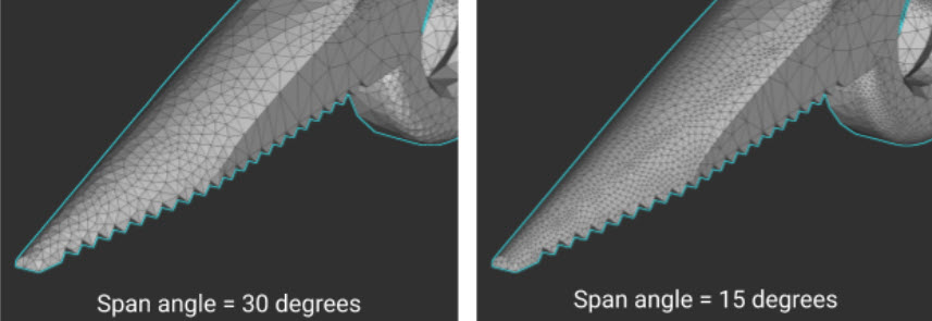
- Growth Rate: Controls how quickly the element size may change between neighboring regions. The value must be greater than 1. Values closer to 1 produce a more gradual transition and a more uniform mesh, while larger values permit more rapid changes in element size.
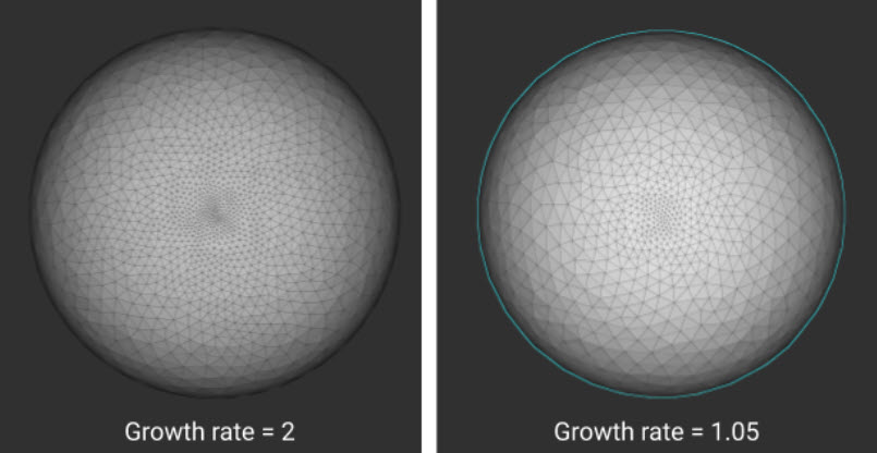
- Feature Angle: Identifies edges to preserve during remeshing. It defines the maximum allowable angle between adjacent faces before it treats their shared boundary as a geometric feature. Lower values preserve more changes in surface direction and may create additional planar regions along curved geometry.
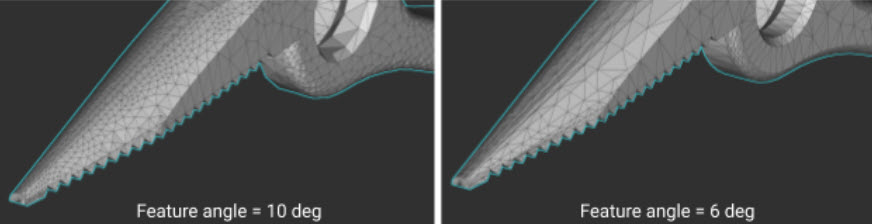
- Min Edge Length: Defines the minimum allowable edge length.
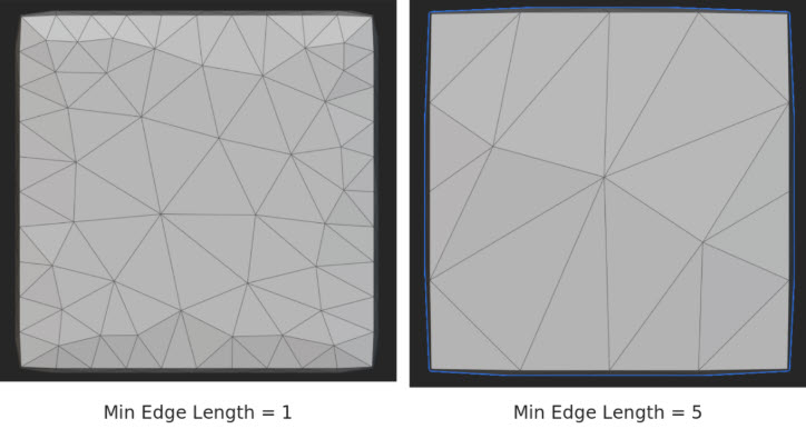
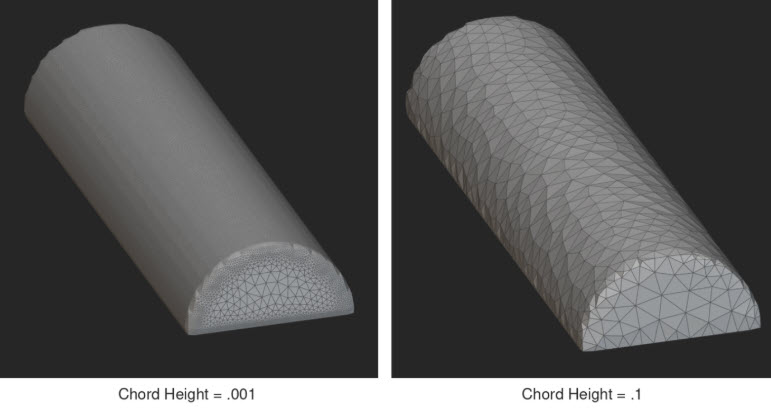
- Chord Height: Defines the maximum allowable distance between the midpoint of a mesh element edge and the input surface. A value of zero disables chord-height-based sizing.
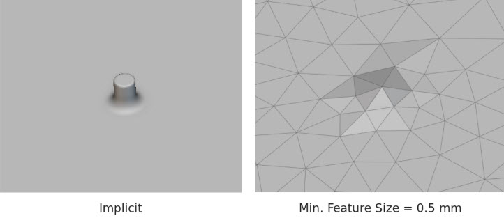
- Min. Feature Size: Specifies the minimum feature size to preserve in the resulting mesh. It removes features smaller than this value. A recommended starting value is approximately 5% of the edge length. Set the value to zero to disable feature removal.
- Preserved Nodes: Accepts a Point List specifying points to preserve as nodes in the resulting FE mesh. If left empty, node preservation is disabled. This input ensures that selected boundary points are retained during remeshing and is covered in greater detail in meshing for Simulation courses.
Back to CAD Methods
As we have learned, an Implicit Body is defined by a function rather than discrete faces and edges. Converting it to a CAD Body requires fitting NURBS surfaces to approximate the geometry, with curvature changes and sharp transitions often creating additional faces. Fine features, such as thin trailing edges or dense lattices, can generate more faces than a CAD system can practically manage. The following back-to-CAD methods suit different geometries and applications. Select an approach based on the geometry’s complexity and the intended downstream use.Quadrangulate Mesh
The Quadrangulate Mesh block remeshes a triangular or quad mesh to produce a quad mesh. Common applications include:- Preparing input for the Cell Map from Quad Mesh block
- Creating or remeshing a quad mesh for export
- Providing input to the CAD Body from Quad Mesh block
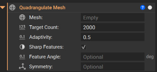
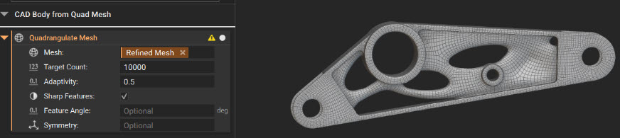
- Mesh: Accepts the mesh to quadrangulate.
- Target Count: Determines the target number of quad elements. If the output mesh is self-intersecting, try increasing the Target Count value or disable the Sharp features input.
- Adaptivity: Adjusts the target quad count to better capture the input mesh curvature; range [0, 1].
- Sharp features: Auto-detects and preserves sharp features in the input mesh.
- Feature angle: Defines the angle used to detect and preserve sharp feature edges in the input mesh. When you provide an input value and the angle between two faces of the mesh is greater than the provided angle, the edge between those faces is tagged as a sharp feature edge. If you don’t provide an input value, an internal algorithm detects sharp edges. This input is used only if the Sharp Features input is checked; otherwise, it is ignored.
- Symmetry: Is an optional input that accepts a frame defining the model’s symmetry plane.
Refine Mesh
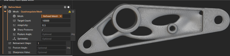
Sometimes you may get an error after using the Quadrangulate Mesh Block, and a warning appears on the block as shown in the image below. The solution is the Refine Mesh block.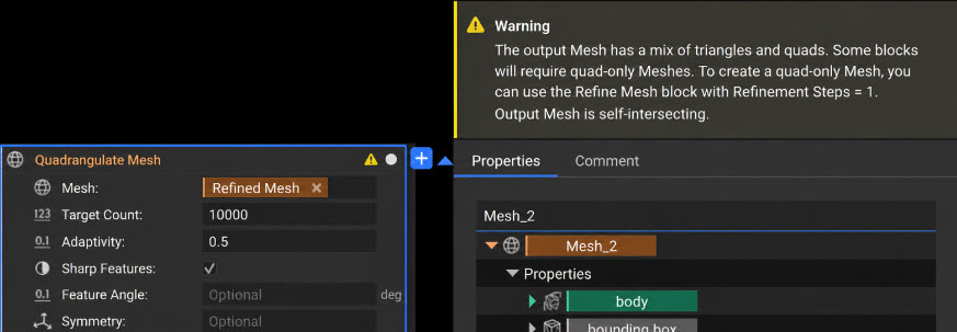
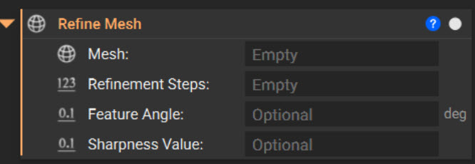
- Mesh: Accepts the mesh to refine
- Refinement Steps: Specifies the number of subdivision iterations (1 to 5).
- Feature Angle: Optionally identifies edges to preserve as sharp. Edges with a dihedral angle greater than this value are treated as sharp during refinement.
- Sharpness Value: Controls the degree of sharpness applied to preserved edges, from 0 to 1. A value of 1 represents an infinitely sharp edge and is the default when a Feature Angle is specified.
CAD Body from Quad Mesh
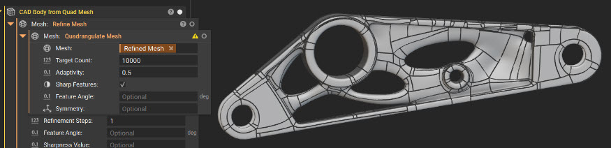
Now that we have learned about meshing and refinement techniques in nTop, we can move on to creating a CAD body. The CAD Body from Quad Mesh block converts a quad surface mesh into a CAD Body that you can export to other CAD applications as a Parasolid (.x_t, .x_b) or STEP (.step) file using the Export Part block.
- Create a surface mesh: Use the Mesh from Implicit Body block to generate a triangular surface mesh.
- Refine the mesh: Use Remesh Surface, Simplify by Threshold, Simplify by Amount, or another refinement method to prepare the mesh for quadrangulation. Before continuing, verify that the mesh contains no meshing errors. A clean, refined mesh enables a more reliable and efficient conversion to a quad mesh.
- Create a quad mesh : Convert the refined mesh using Quadrangulate Mesh
- Refine the quad mesh : If necessary, apply Refine Mesh to improve detail retention and reduce rounding near sharp edges.
- Create a CAD Body: Use the CAD body from Quad Mesh block and input the refined quad mesh.
Note: The Export section of this lesson covers exporting the resulting CAD Body.
CAD Body from Implicit Body (BETA)
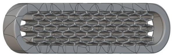
The CAD Body from Implicit Body block is a BETA block that converts an Implicit Body into a CAD Body for export to other CAD applications. You can export the resulting body as a Parasolid (.x_t, .x_b) or STEP (.step). This method is intended for medium-complexity textured models and lattices, including:- Beam- or face-based lattices with up to 10,000 beams or faces
- TPMS lattices with up to 1,000 unit cells
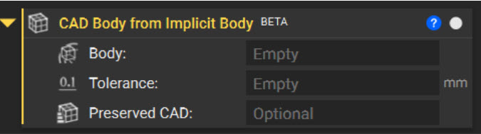
- Body: Input accepts the Implicit Body to convert.
- Tolerance: Defines the maximum permitted deviation between the CAD Body and the input Implicit Body. Increasing the tolerance generally reduces the face count and conversion time but produces a less accurate approximation. Begin with a value approximately half the size of the body’s thinnest feature.
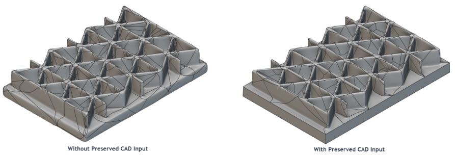
- Preserved CAD: Accepts an optional list of CAD Bodies containing faces to incorporate into the output. The block attempts to stitch eligible faces into the resulting CAD Body. Faces that extend beyond the Implicit Body’s surface or cannot be stitched successfully are ignored.
Simplified Body Representation
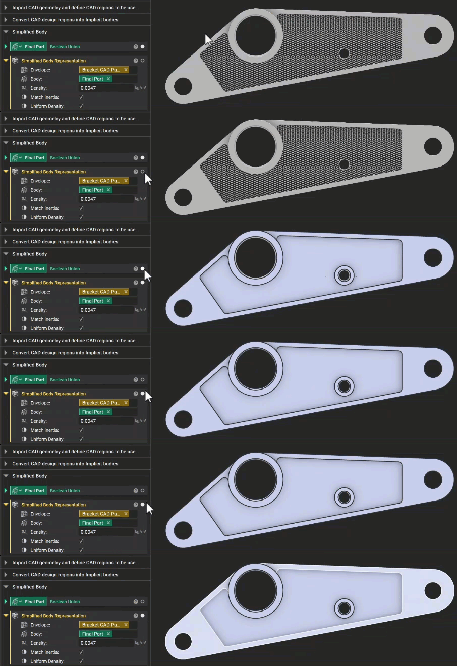
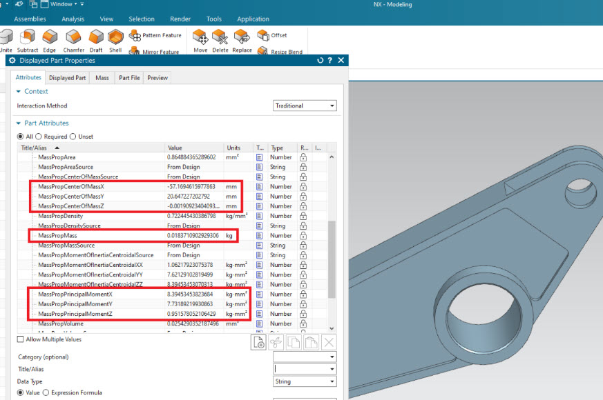
The Simplified Body Representation block creates a simplified boundary envelope of a complex Implicit Body while preserving its mass properties. Overall mass is always matched, with the option to also preserve the center of gravity and moments of inertia. This method is recommended for high-complexity geometry that would produce too many B-rep faces for traditional CAD systems, including:- Fine surface textures
- Beam- or face-based lattices with more than 10,000 beams or faces
- TPMS lattices with more than 1,000 unit cells
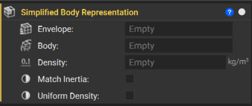
- Envelope: A list of CAD Bodies defining the simplified external boundary.
- Body: The implicit body to simplify.
- Density: The material density assigned to the body.
- Match Inertia: Specifies whether the output should also preserve the center of gravity and moments of inertia.
- Uniform Density: Creates an output compatible with CAD systems that do not support variable-density parts. SolidWorks users should enable this option to preserve the correct center of gravity and moments of inertia.
Reference Geometry for CAD Reconstruction
As you learned in earlier lessons, nTop uses precise curves, including lines, arcs, conics, and splines, to construct implicit geometry. You can export these curves with relevant numerical parameters to support automated or manual surface reconstruction in CAD, especially for parts requiring highly tailored surfaces.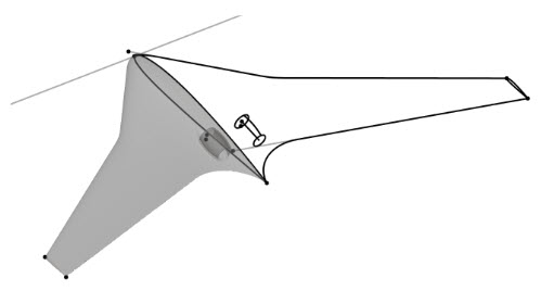
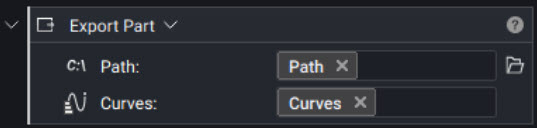
Note: The Export Part block includes multiple overloads. Use the Path, Curve and Path, Curve List overloads for this process.
Convergent Body (BETA)
Some CAx software using Siemens Parasolid, such as NX or STAR-CCM+, supports a geometric representation known as Convergent Modeling. In this format, mesh face groups are treated as CAD faces within the topology, in addition to analytical and NURBS faces. This supports many downstream operations that mesh formats typically don’t support in the same software. nTop supports convergent body exports where each face group is defined by a mesh. Convergent Bodies are created using either the Convergent Part from Named Body or the Convergent Body from Multi-Region Mesh blocks. These workflows will be introduced in a separate course that explores meshing in nTop in greater depth.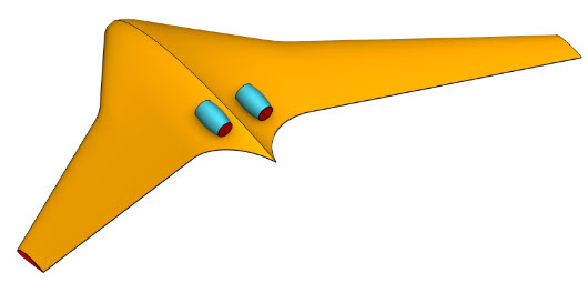
Exporting Parts
To export an Implicit Body from nTop, it must first be converted to a supported file type using one of the methods described above. The following steps outline how to export the converted part.Exporting Meshes
The Export Mesh and Export 3MF blocks, located under Utilities > Exchange, export mesh geometry in STL, OBJ, PLY, or 3MF format. STL offers the broadest compatibility, while 3MF files are typically about one-third the size for equivalent geometry and support color and multi-body assemblies.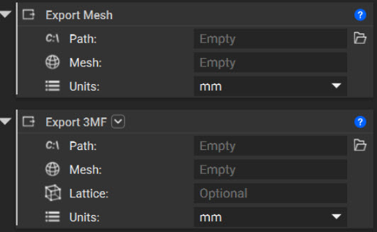
Note: The Export 3MF block includes an option to export a thickened lattice. Only beam-based lattices are supported. If the input lattice does not have a defined thickness, it automatically applies a default thickness of 1 mm. For detailed instructions, see How to Export a 3MF File.
Exporting CAD
The Export Part block exports CAD parts from nTop. Before exporting, convert an Implicit Body to a CAD Body using either the CAD Body from Quad Mesh block or the CAD Body from Implicit Body block, as described above. Parts can be exported as Parasolid (X_T, X_B), STEP, or IGES files.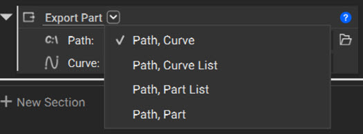
Note: The Export Part block includes multiple overloads for different input types. Select the overload that matches the geometry you want to export, or drag a compatible block into the input to update the overload automatically.
Export for Additive Manufacturing
All slicing tools are in the Manufacturing tab. You can export multiple slice file formats. To learn more about slicing for additive manufacturing, check out our course, 250: Slicing and Print Layout.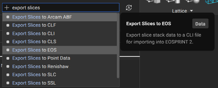
Exporting Implicits
The Export Implicit Body block, located under Utilities > Exchange, exports an Implicit Body as an .implicit file. This format preserves the underlying implicit function rather than an approximated or tessellated representation, maintaining full geometric fidelity while typically producing a file significantly smaller than an equivalent mesh. As introduced in Course 1, this workflow uses Implicit Interop and requires the receiving application to support the .implicit format.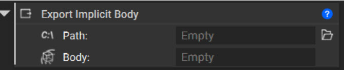
What to Take Away
- Surface meshing converts an Implicit Body into a discrete representation of its boundary for downstream manufacturing, simulation, and visualization workflows.
- A clean mesh should be closed, manifold, oriented, and free of self-intersections.
- Meshing and remeshing parameters balance geometric fidelity, element quality, file size, and computation time.
- The appropriate back-to-CAD method depends on geometric complexity and the intended downstream application.
- Complex geometry that is impractical to convert into a full CAD Body can be represented using a Simplified Body Representation block that preserves critical mass properties.
- nTop geometry can be exported as mesh, CAD, reference geometry, additive manufacturing, or .implicit files, depending on the capabilities of the receiving application.