

Before we start: a thought experiment
Imagine you’ve spent the last three weeks lofting the outer mold line (OML) of a new aircraft fuselage—the continuous aerodynamic skin that defines the aircraft’s external shape. Every other component must either fit within it or blend seamlessly into it. The nose cone transitions smoothly into the center fuselage and tail cone, wing and empennage fairings are carefully integrated into the surface, duct cutouts are incorporated, and dozens of splines maintain the “Class A” surface continuity required for aerodynamic performance. Then the aerodynamics team walks over: “We need 12 configurations for tomorrow’s trade study—different fineness ratios, three wing sweep angles, and a stretched variant with two additional fuselage sections. Can you update the OML for all of them?” In a traditional CAD system, that’s a risky request. Stretch the fuselage too far or sweep the wing beyond the range the fairing was designed for, and the surface operations that built the original model may fail to regenerate, or worse, regenerate into an invalid or unusable geometry. What should be a simple design change can quickly turn into hours or days spent repairing broken geometry. This lesson introduces the geometry engine beneath nTop that changes that equation: implicit modeling. You’ll learn how its mathematical representation makes complex geometry faster to generate, more reliable to modify, and easier to automate.So, What Is nTop?
Before going further into how nTop works, it’s worth pausing on what it actually is. nTop is computational engineering software built for exactly the kind of problem you just read: cases where geometry itself is the bottleneck. nTop is computational engineering software for workflows in which geometry becomes a bottleneck. It helps engineers create and iterate on complex, performance-driven geometry that would be difficult or inefficient to build using traditional CAD alone. You’ll find it embedded in workflows across aerospace, defense, and automotive — anywhere teams are pushing toward designing faster. The common thread: geometry that is especially complex, highly iterative, or difficult to scale efficiently in traditional CAD. To help you understand what makes nTop unique and how it enables rapid iteration for high-performance designs, let’s hear directly from our founder, who will explain the vision and principles behind the platform.What Is Implicit Geometry? (And How Is It Different From B-Rep?)
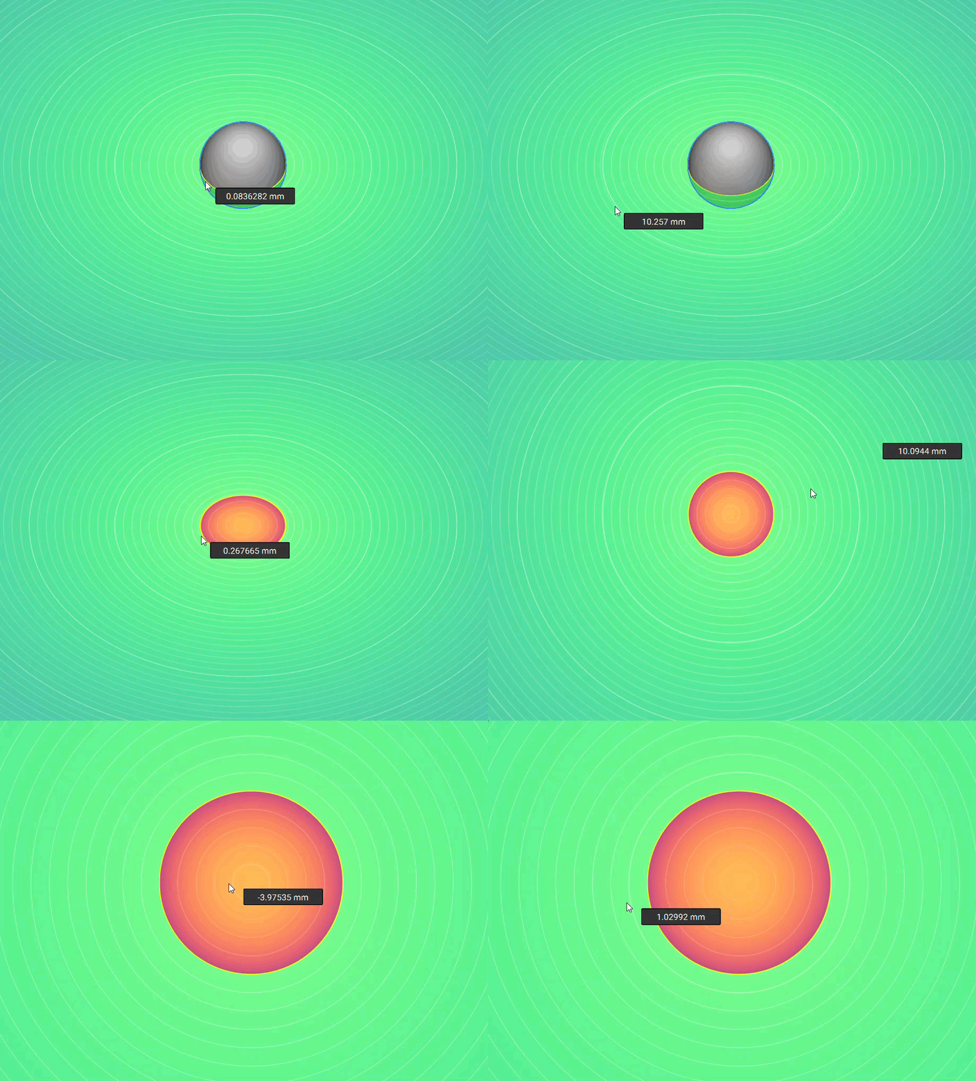
Nearly every traditional CAD system represents geometry as a boundary representation (B-rep): a watertight skin made up of faces connected by edges and vertices. When you select a rounded corner or planar surface, you’re interacting with an actual face that has been explicitly created and stored by the CAD system. nTop takes a fundamentally different approach. Instead of storing faces, it represents geometry mathematically using a signed distance field (SDF)—also known as an implicit function or i-function. Rather than describing the boundary directly, this function can be evaluated at any point in 3D space and returns a single value:- Negative → the point is inside the body
- Positive → the point is outside the body
- Zero → the point lies exactly on the surface
What implicit geometry is not
New users often ask, “Why can’t I click on a face?” The answer is simple: there isn’t a persistent face to click. nTop doesn’t store geometry as faces, edges, and vertices. Instead, what you see is a visualization generated from the underlying mathematical field. This is intentional. In traditional CAD, selecting a face creates a dependency on that specific piece of topology. If the geometry changes enough, that face may disappear, causing downstream features to fail. In nTop, workflows are built from mathematical relationships and parameters instead of face references, making them far more robust to large design changes.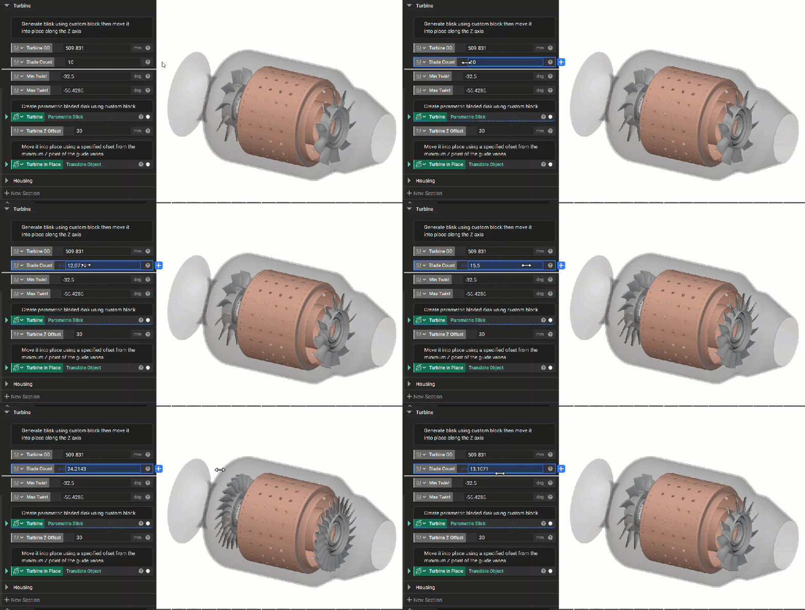
The Programmatic Nature of Implicit Geometry
Because geometry is represented mathematically, an nTop model is a graph of operations rather than a stored shape. The nTop Notebook is the workspace where you build and organize an nTop model as a sequence of connected operations. Each block acts like a function, taking typed inputs and producing an output that feeds downstream operations. Data flows through the notebook much like variables flow through a program, resulting in a 3D design. If you’ve worked with a CAD model tree, the nTop Notebook will feel familiar. Both record modeling operations and let you change earlier inputs to rebuild the model. The difference is what those operations depend on. A CAD feature may reference specific topology — a fillet on specific edges or an extrude from a specified sketch. An nTop block stores a function and its inputs, so it isn’t tied to a particular face or edge. Change something upstream, and the block simply re-evaluates.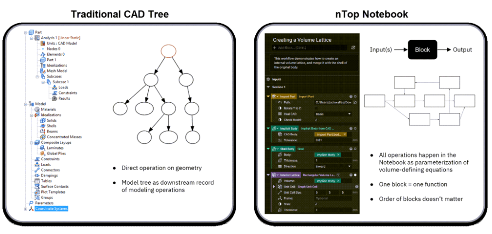
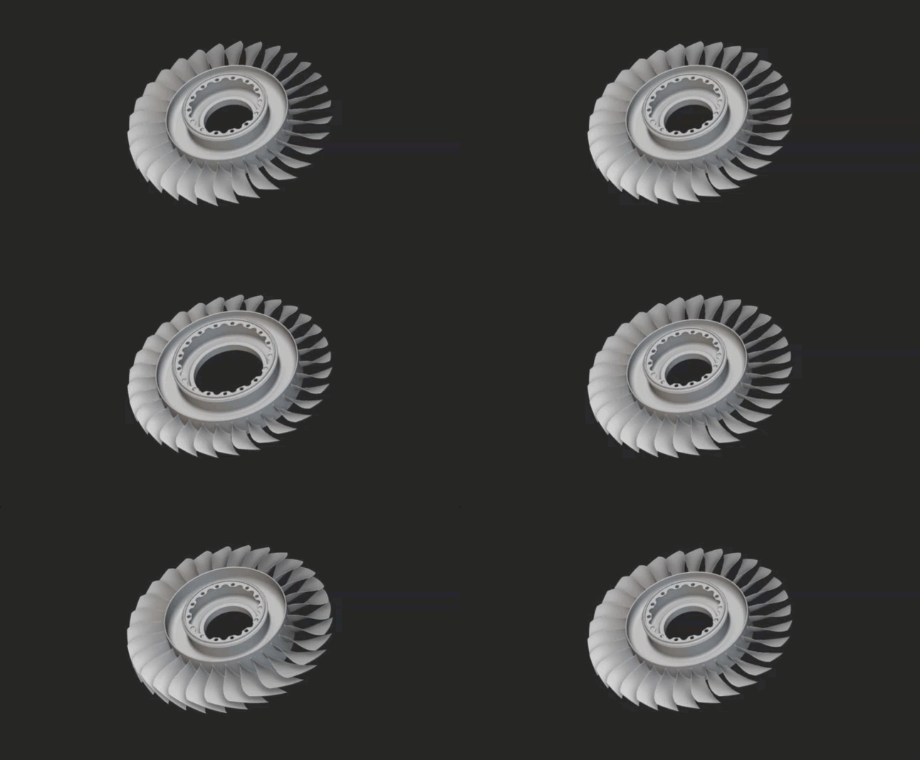
Why nTop Uses an Implicit Geometry Engine
Speed of compute
An implicit body is defined by mathematics, not topology. Instead of solving complex surface intersections, many geometric operations can be expressed as direct field evaluations rather than repeated surface-intersection and topology calculations. The efficiency gains can be dramatic. A gyroid lattice, for example, is described by a single equation: F(x,y,z) = cos(x)sin(y) + cos(y)sin(z) + cos(z)sin(x)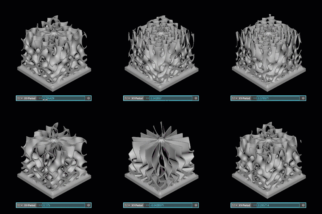
Robustness across wide parameter variations
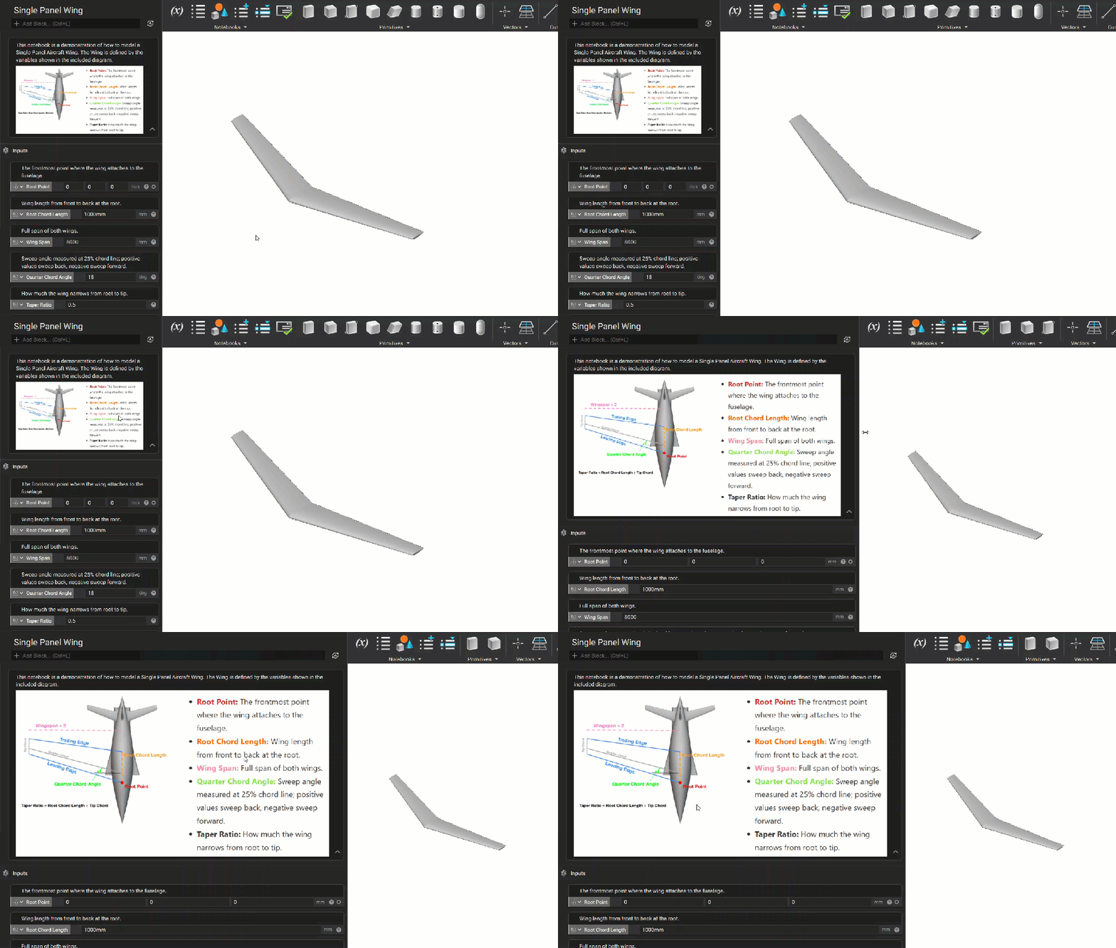
Recall the “12 fuselage configurations by tomorrow” scenario. In a B-rep workflow, major parameter changes can invalidate downstream booleans, fillets, and blends because those features depend on maintaining valid faces, edges, and intersections. In an implicit model, the same operations are derived directly from field functions. For example, the union of bodies A and B is represented by min(F_A, F_B). Offsets, shells, and blends are likewise defined mathematically rather than by trimming and stitching new surface topology. Because downstream operations do not depend on persistent face or edge identities, large geometric changes are less likely to create broken references. This makes implicit workflows well-suited to design exploration and unattended parameter studies.Scalability and automation
Speed and robustness make automation at scale practical. Instead of manually rebuilding 12 fuselage configurations, the same notebook can be evaluated using 12 parameter sets for wing sweep, fineness ratio, and fuselage length. The same approach extends to optimization and generative studies involving hundreds or thousands of variants because the workflow captures reusable computational logic rather than referencing specific faces and edges.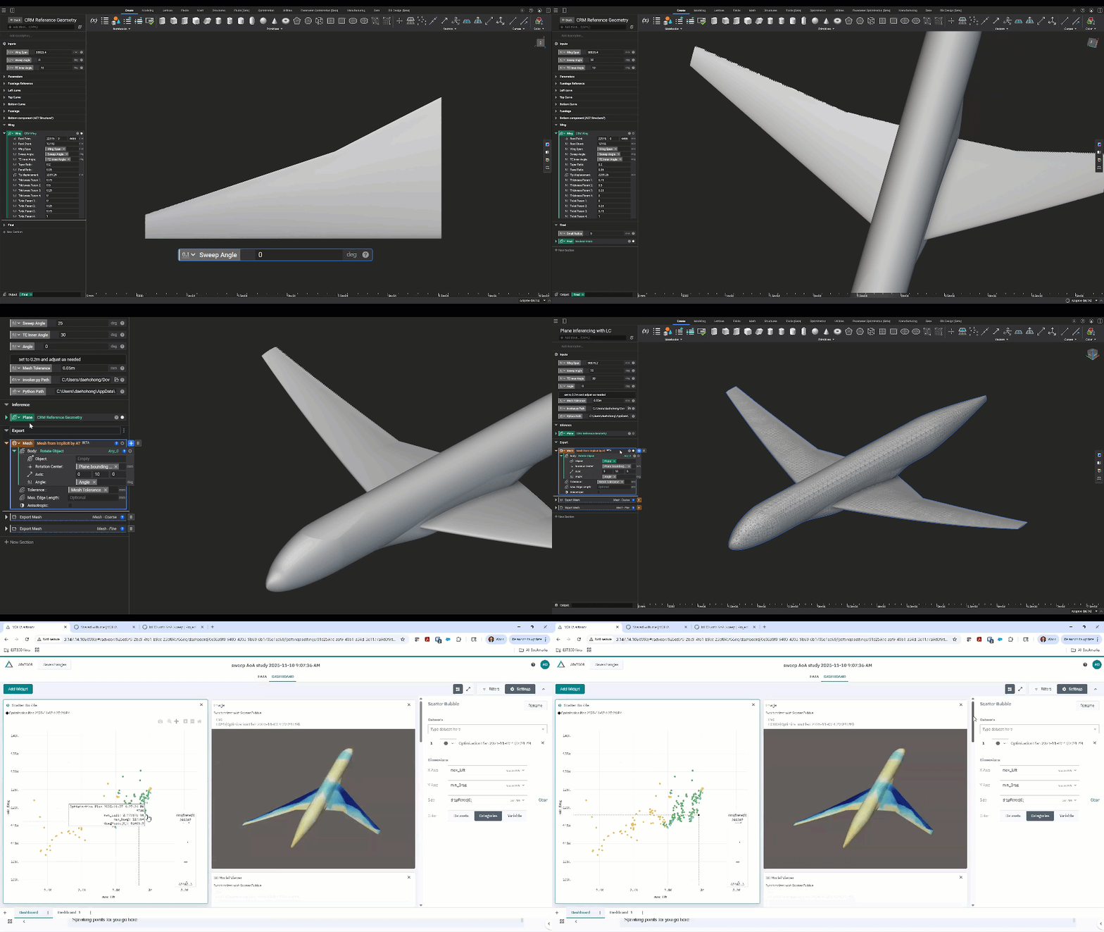
Using Implicit Geometry Downstream
Eventually, the equation becomes something tangible: a machinable file, an analysis-ready mesh, or an assembly drawing ready for sign-off.Manufacturing
Because the field can be evaluated at any point, nTop can generate a mesh at whatever resolution the process actually needs: coarse for a quick visual check, fine where the process resolves fine features. For additive processes, it can skip the mesh entirely and produce the layer-by-layer slice data that the machine consumes directly from the implicit body. That path matters most for exactly the geometry that gives conventional exporters trouble — a lattice fine enough to produce an unmanageable mesh is no harder to slice than a solid block.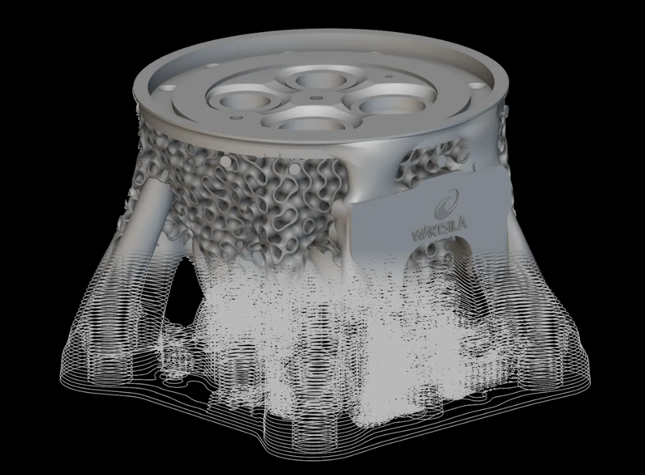
Simulation
The same evaluation-on-demand applies to analysis. Engineers can generate a finite element model and export it to established CAE tools, or run analysis inside nTop. Bringing simulation results back into nTop opens the door to more advanced capabilities. Simulation results — stress, displacement, temperature — come back into the nTop workflow as fields, which can drive geometry parameters. For example, more material can be placed where the loads are, and the design responds to its own performance rather than to a designer’s estimate of where the loads will be. Later in the course, we’ll explore how simulation results can directly shape geometry through a concept called Field-Driven Design.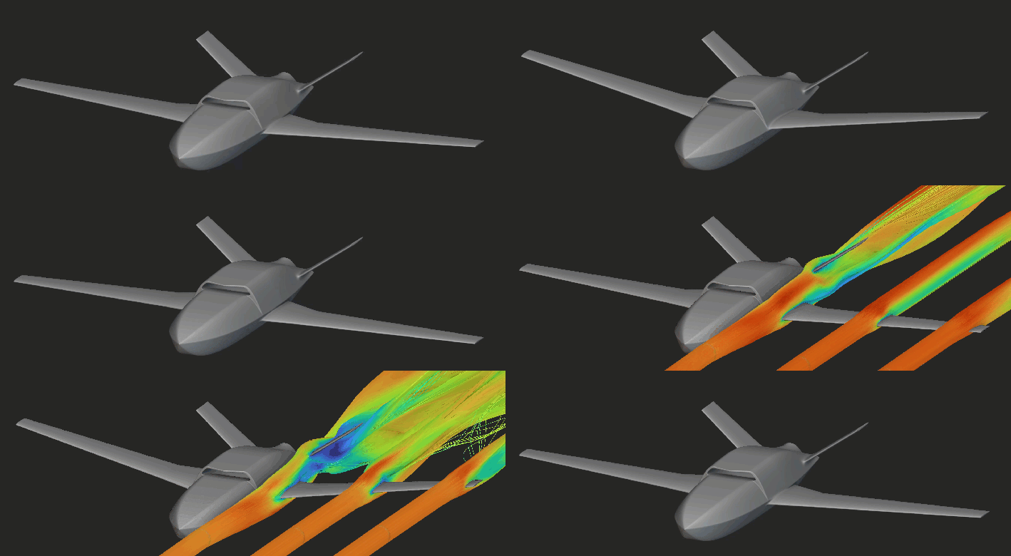
CAD and the rest of the digital thread
Here, the limit isn’t nTop; it’s what the receiving system can hold. Traditional CAD stores every face explicitly—precisely the cost implicit modeling avoids—so a part with millions of lattice faces may be too complex for a CAD system to represent efficiently. nTop addresses this by matching the representation to the downstream need. Simpler parts, such as topology optimization results, can be converted to full B-rep solids. More complex parts, such as those with intricate lattices, can be represented by a simplified envelope that preserves properties such as weight, center of gravity, and moments of inertia. These exports let designs move into CAD for clearance checks, assemblies, drawings, and other downstream activities without carrying unnecessary geometric detail. nTop also leverages precise curves (lines, arcs, conics, and splines) for implicit geometry construction, which can be exported downstream along with numerical parameters. This data can serve as a reference for automated or manual surface construction in CAD for parts that require highly tailored surfaces. From there, nTop can fit into the broader digital thread, with design outputs passing through CAD and into existing PLM systems for product data management and lifecycle processes. The goal is not to force maximum geometric fidelity into every system, but to provide the representation and data each stage of the product development process needs.Implicit interop: Handing over the function itself
Every path described so far is a conversion, and every conversion has a trade-off. A mesh, voxel grid, or slice stack is an approximation with a tolerance difference at the time of export. Increasing accuracy increases file size—sometimes dramatically. The exported result is also inert: a collection of triangles or faces with no knowledge of the rules that produced it. There is a fourth path that avoids the conversion entirely. Rather than exporting an approximation of the body, nTop can export the implicit body itself — the function — in a compact file that a receiving application evaluates on demand. Nothing is tessellated, so nothing is lost. Files are typically generated in under a second and can be a small fraction of the size of the equivalent mesh. This works in two ways. Some partner applications read the format natively: EOS’s build preparation software, for instance, can import an nTop implicit body and prepare it for printing without a mesh anywhere in the chain. Teams can also build their own integrations, calling a library that loads an implicit file and answers questions about it — the location of the surface, the overall volume, and the slice information at a given plane. The geometry stays exact all the way to the machine. There’s a practical side benefit worth knowing. An implicit file carries the shape but not the notebook that generated it, allowing a supplier or partner to receive the buildable geometry without the engineering logic behind it The limitation is straightforward: this path only works where the receiving end knows how to evaluate a field. Most of the CAD and CAE world still expects boundaries, which is why the conversion routes described in earlier sections are frequently used. Implicit interop is the direction the ecosystem is moving in, but not yet the default.
The handoff runs one way
Whatever path you take, note the direction. An exported mesh or CAD body is a snapshot of the design at one set of parameter values. Editing that snapshot in another tool does not update the notebook that produced it. When the design changes, you don’t repair the export — you change the parameters and regenerate it. This is also why traditional CAD stays in the picture. It remains the better alternative for assemblies, mechanisms, drawings, and manufacturing documentation. nTop’s strength is upstream of all of that: generating and iterating the geometry itself.What to Take Away
- B-rep stores a surface; implicit stores a function. Instead of faces, edges, and vertices, nTop stores a signed distance field that can be evaluated at any point in space to determine whether that point is inside, outside, or on the body.
- There’s no face to click because no face is stored. What you see on screen is a visualization generated from the field, not the geometry itself.
- A model is a graph of operations, not a shape. The notebook captures the engineering logic — rules, relationships, and parameters — and re-runs it whenever an input changes.
- Complexity costs far less. A gyroid is one equation whether it has 1,000 cells or 1,000,000. On a 10,000-cell heat exchanger, that meant 2 minutes instead of 6 days, and 1.3 MB instead of 1.5 GB.
- Large design changes don’t break the model. Nothing downstream depends on a specific face or edge that a parameter change might destroy, so operations that would fail in a B-rep workflow simply re-evaluate.
- Robustness is what makes automation practical. Twelve fuselage configurations become twelve parameter sets in one model, not twelve manual rebuilds — and the same logic scales to hundreds.
- The implicit model is the source, and everything else is generated from it. Meshes, CAD bodies, and machine files are produced at the fidelity each downstream tool needs; when the design changes, you regenerate them rather than repair them.