
Applies to
- Vector field definition and evaluation
- Applying surface forces to cylindrical geometry
- Distinguishing between circumferential and radial force directions
- Structural simulation preparation workflows
Procedure
- Create the reference geometry:
- Add a Circle block with the following settings:
- Center point: 0, 0, 0
- Radius: 25 mm
- Normal: 0, 0, 1
- Define the force magnitude:
- Create a Scalar Variable named F and set it to 1 N.
- Construct the Circumferential Force field:
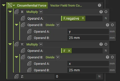
- Add a Vector Field from Components block and name it Circumferential Force. Use the following math expressions:
- X: -(F * y / 25 mm) // Tip: Use the negative of the F variable we created in the above step to avoid multiplying by -1
- Y: F * x / 25 mm
- Z: 0
- Generate evaluation points:
- Use a Equidistant Points on Curve block:
- Curve: Your Circle from Step 1.
- Increment: Length/8 (to create 8 equidistant points).
- We will use a Sub List here to exclude the start point, which is counted twice.
- Evaluate the field:
- Add an Evaluate Field block:
- Vector Field: Circumferential Force
- Points: The point list from Step 4.
- Verify the results:
- Inspect the evaluated output. For a pure circumferential field, the sum of all X and Y components should be zero, indicating no net translation, only torque.
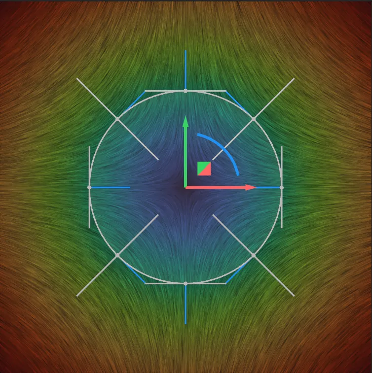
Switching to a Radial Field
To convert the field from circumferential to radial, swap the coordinate inputs so each component is driven by its own axis.Testing and Verification
Visual Check — Viewport Streamlines
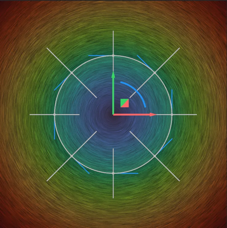
Preview the vector field in the nTop viewport from the Top View (Ctrl+5).- Correct: Streamlines appear as smooth, concentric arcs flowing uniformly around the circle. You can also extract the Normals at the different points to see what direction it is pointing at.
- Incorrect: If streamlines show a “saddle pattern” (curving inward toward the axes), you have likely mapped same-axis components (Radial) instead of cross-axis components (Circumferential).
| Circumferential CCW | Radial |
|---|---|
 |  |
Net Force and Torque Check
- Sum Fx: Should equal 0.00 N (No net force in X).
- Sum Fy: Should equal 0.00 N (No net force in Y).
- Total Torque: Calculated as should equal 200 N·mm for F = 1\text{ N} across 8 nodes at r = 25\text{ mm}.