
Working with CAD
nTop supports both multi-body parts and assemblies and treats CAD imports as collections of bodies; even if the import only contains a single body. Some operations require identifying the specific CAD body or face by creating a CAD body or face variable.Extraction by Manual Selection on Screen
Extraction by Manual Selection on Screen
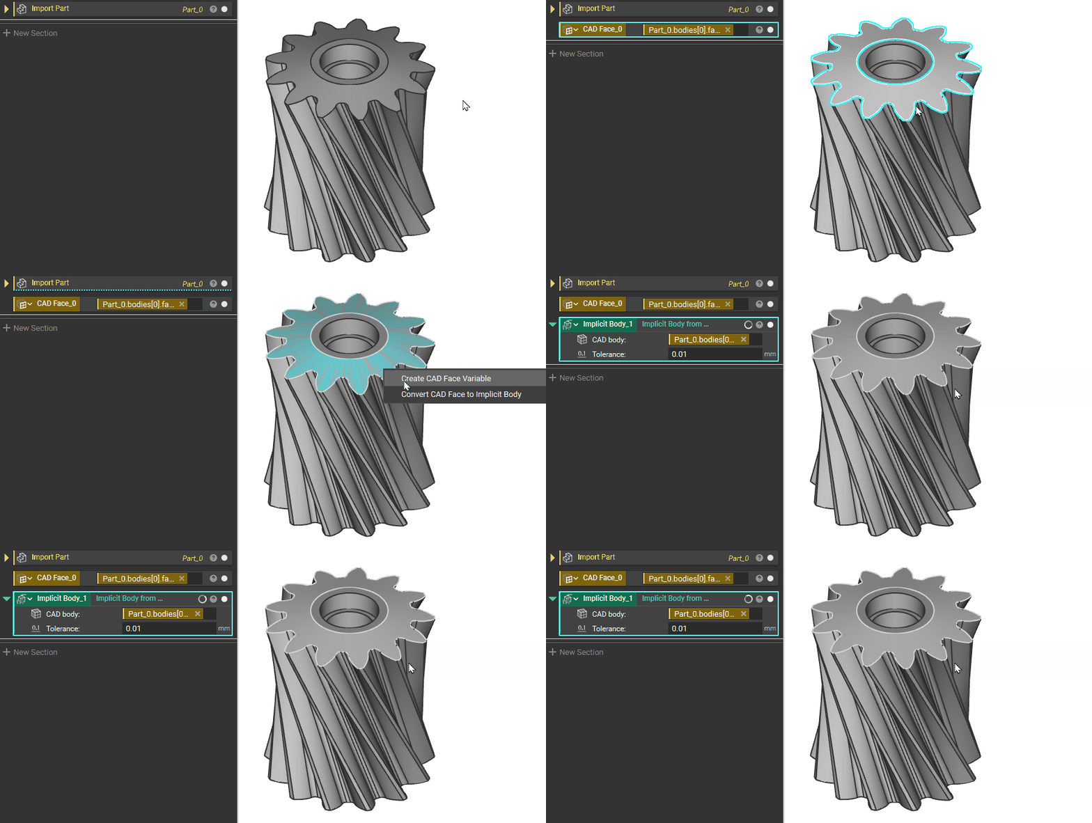
The quickest way to convert an imported CAD part into an implicit body is to extract directly from the part shown on the screen. Both the CAD Body and Face can be converted into implicit bodies as well as made into CAD Body or Face Variables.Double-Click to select the whole body, then right-click to either “Create CAD Body Variable” or “Convert CAD Body to Implicit Body”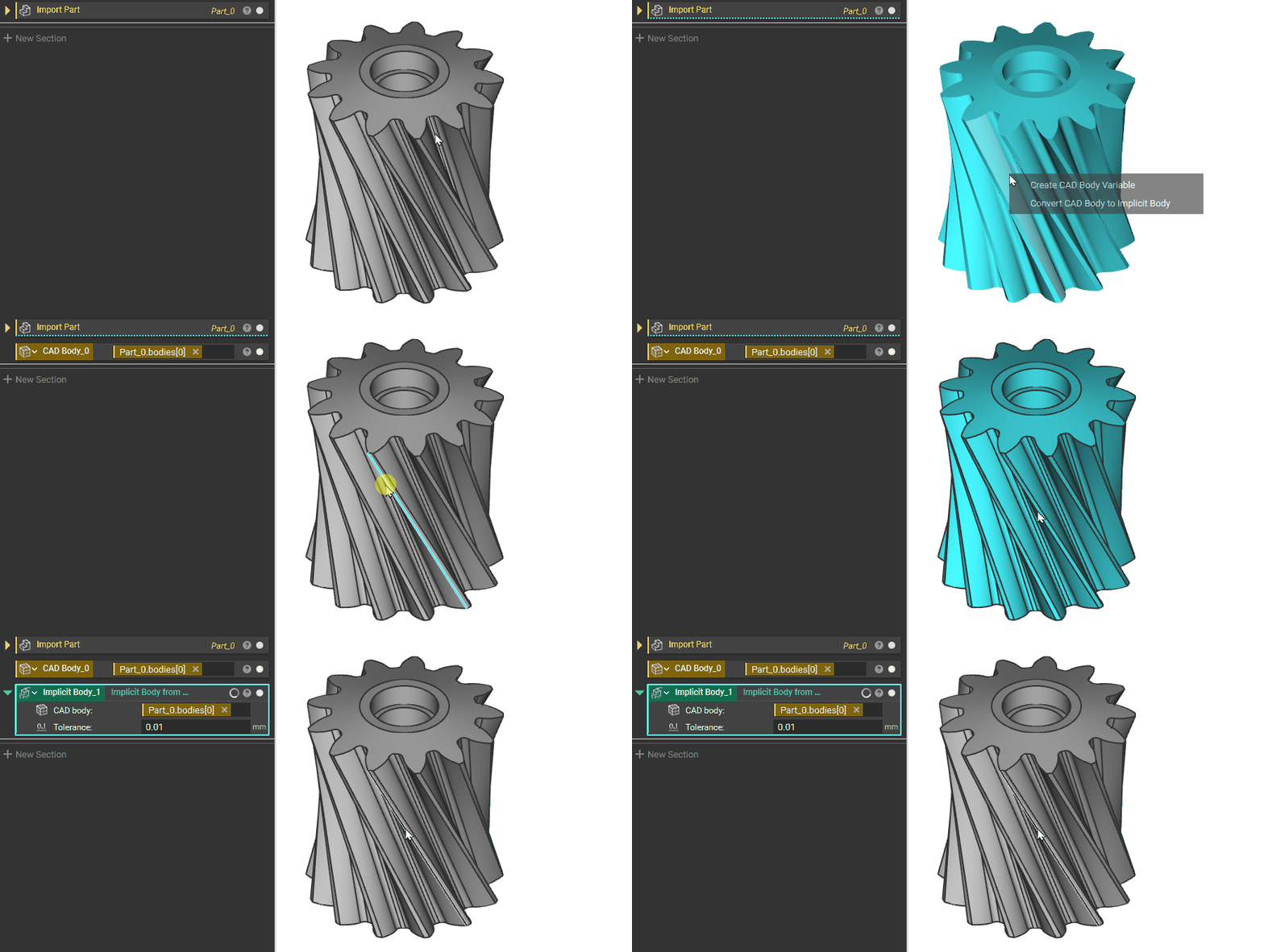 Single-Click to select a face, then right-click to either “Create CAD Face Variable” or “Convert CAD Face to Implicit Body”
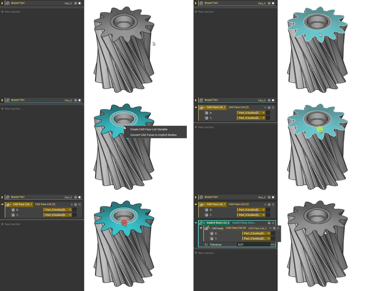
 Hold Ctrl to select more than one body or face, then “Create CAD Body List Variable” or “Convert CAD Body to Implicit Bodies”. A List is created if more than one item is selected.In this example, we choose 2 faces, so the block will have a (2) behind its name, with 2 being the size of the list.
 Edges or vertices can also be extracted the same way, but they can only be made into CAD Vertex or CAD Edge Variables and not implicit bodies.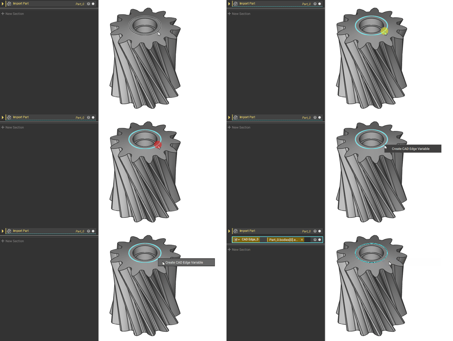
Extraction by Properties
Extraction by Properties
Open the Properties Panel of the Imported part. Expand the Bodies Properties until you reach the desired element. Drag it into the Notebook to create a block from it.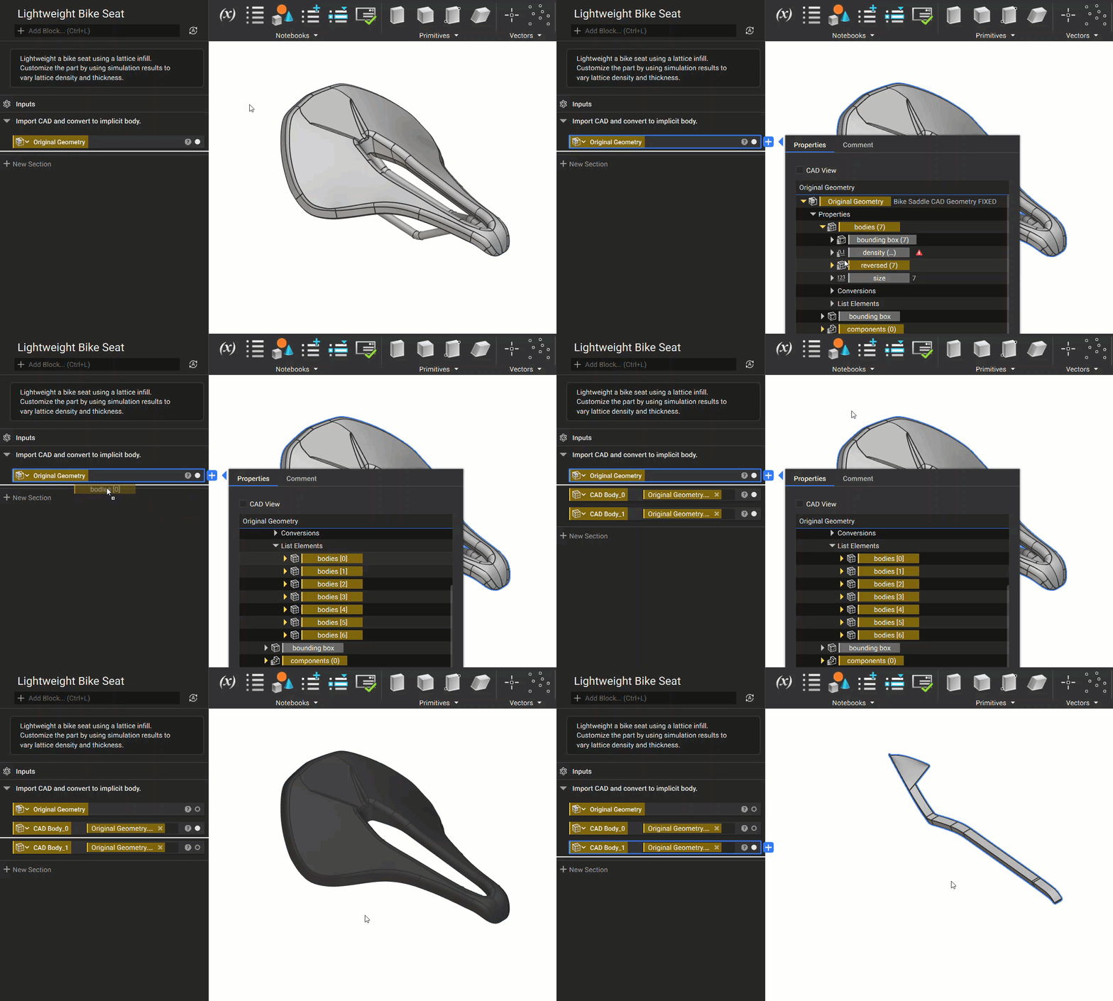
Extraction by Properties Using CAD View
Extraction by Properties Using CAD View
When opening the properties panel of an imported CAD part or assembly, there are many property chips to choose from. To simplify extraction we added a CAD View filter, which hides all properties except for CAD bodies.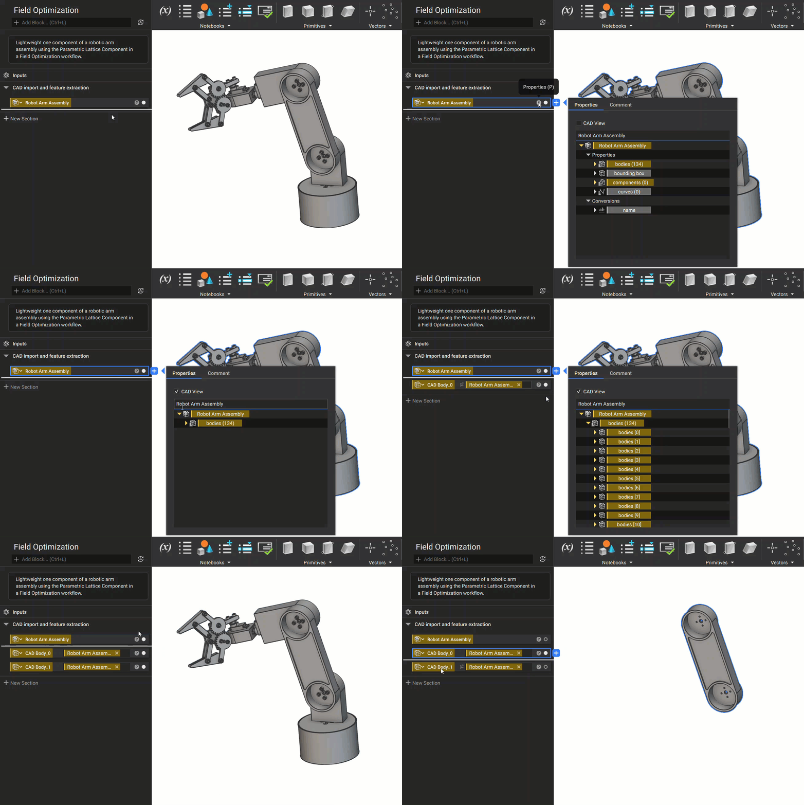
Extraction by CAD Blocks
Extraction by CAD Blocks
In nTop 5.8, we released a series of new blocks that are designed to help users interact with CAD bodies more efficiently.To extract CAD Faces:Use the Get CAD Faces block: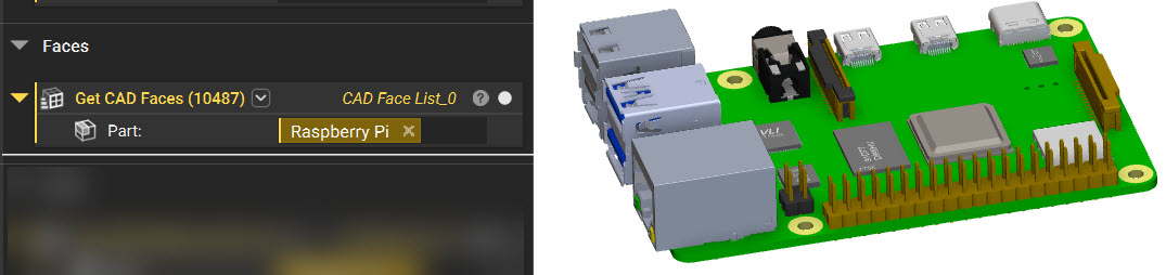 To extract CAD Bodies:Use the Get CAD Bodies block:
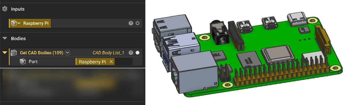 You can also use the Get CAD Bodies by Name or Get CAD Faces by Name block to further refine your selections: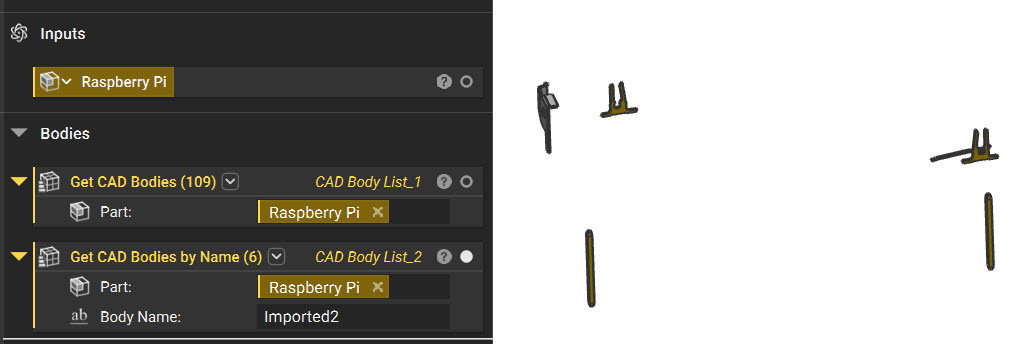
Extraction by Color Blocks
Extraction by Color Blocks
You can extract CAD Faces and CAD Bodies using our two color based blocks: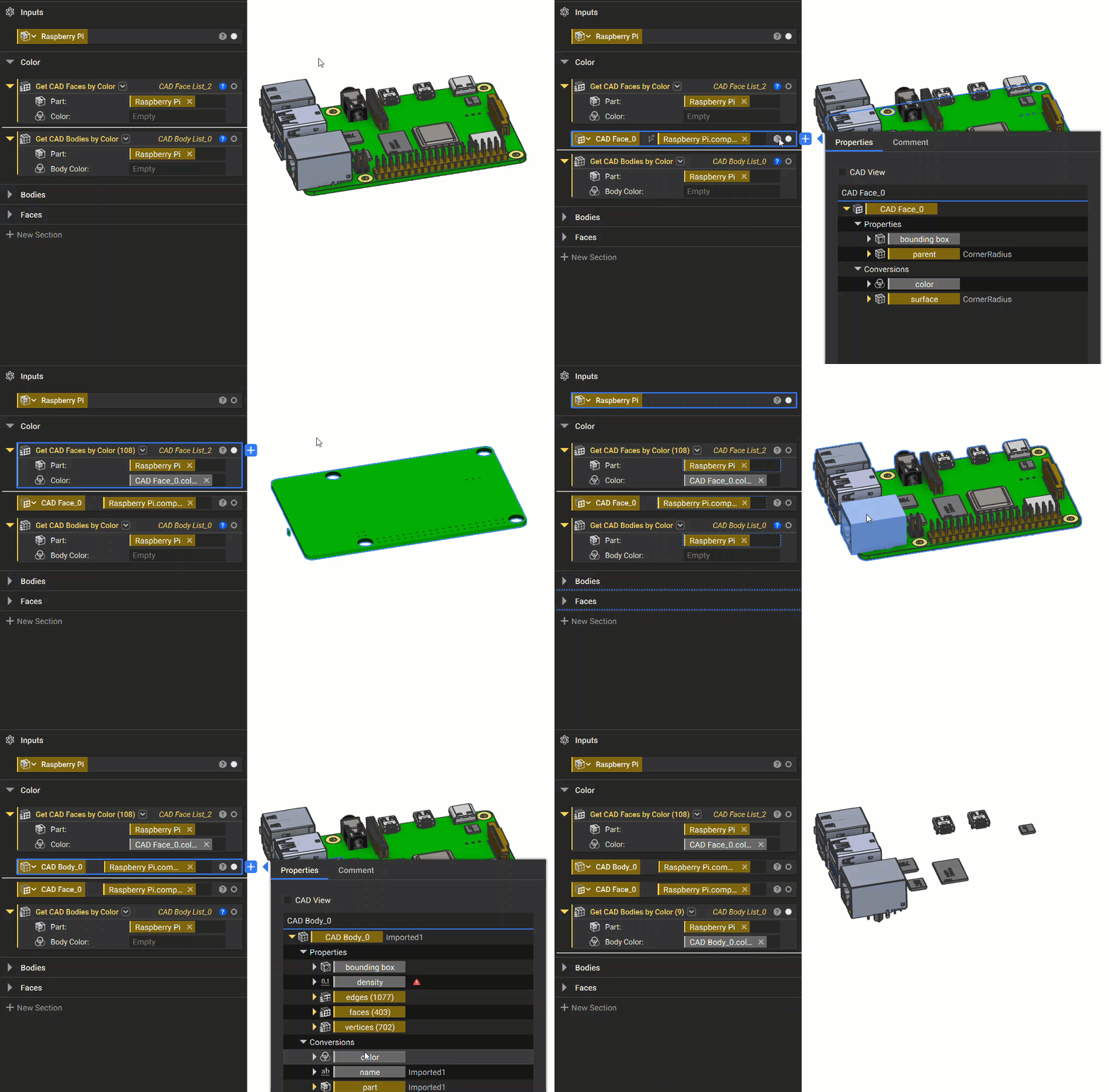 If you import your CAD part and it doesn’t have any color, make sure you change the Display Mode to “CAD Color”.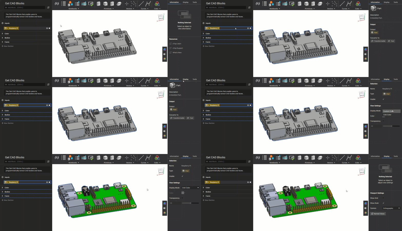
- Get CAD Faces by Color
- Get CAD Bodies by Color
Turning Multiple CAD Faces into a Single Surface
Turning Multiple CAD Faces into a Single Surface
Create a CAD Face List of faces you want to merge, then use the Stitch CAD Surface Bodies or the Stitch Adjacent CAD Faces block. These blocks merge multiple sheets within a tolerance range and output the results as a list.This block comes auto-populated with a list, however. You cannot input a list into a list. You need to delete the auto-populated list to input the CAD faces.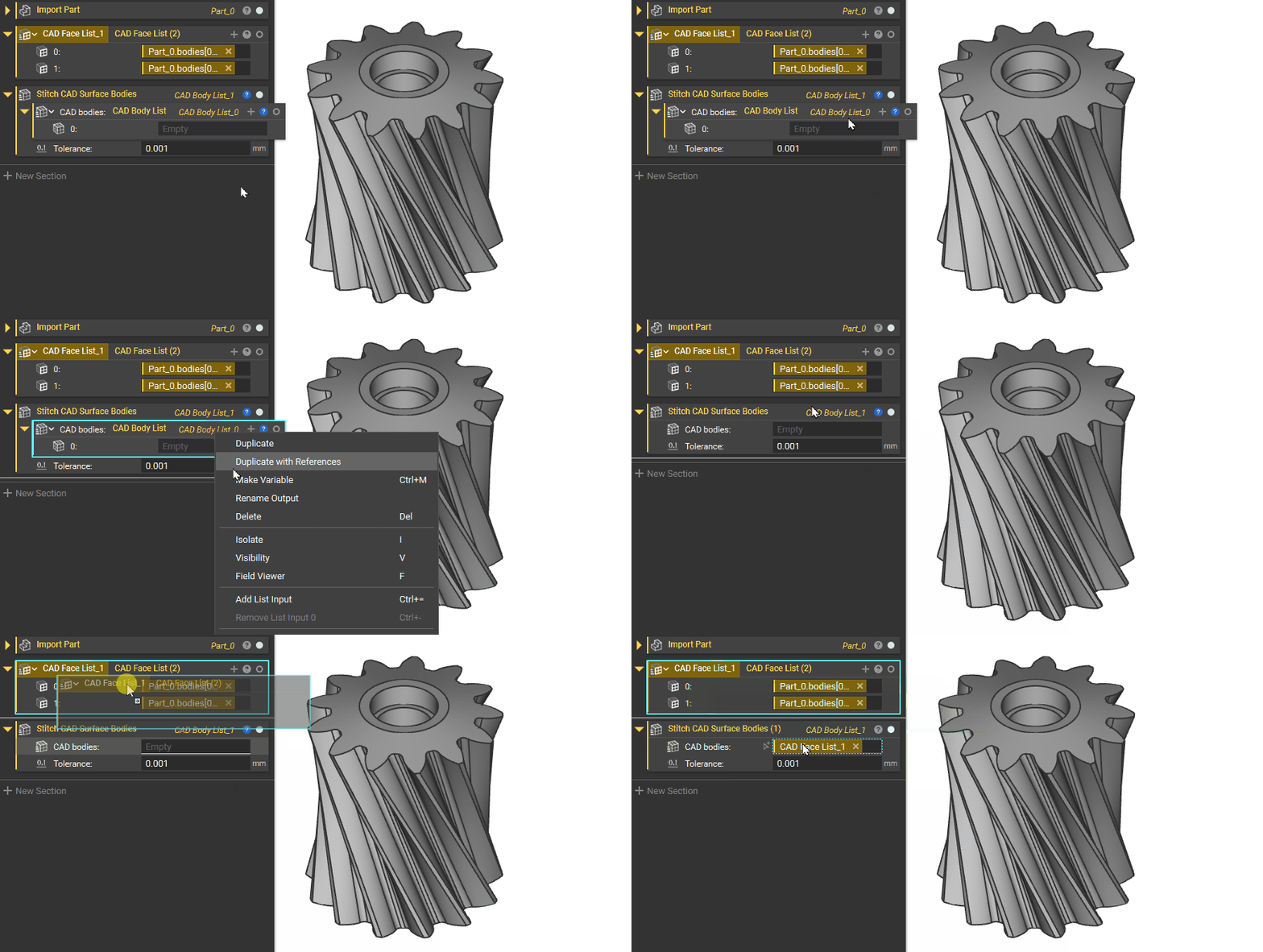
Optional Challenge Problem
Estimated Time to Complete: 25 minutesChallenge Problem Statement
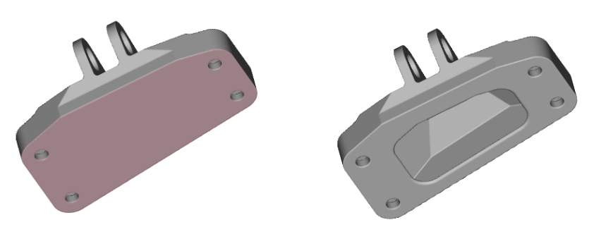
Feel free to try our nTop Essentials challenge problem after completing the optional test problem. Given the CAD file below, shell the part with a 3mm wall thickness inwards and add a hole for powder removal. Then, mesh the part with a 1mm tolerance and export it as a 3MF. For an added challenge, the hole for powder removal should resemble the shape highlighted below. Your final result should look something like the second image if you choose to create a hole resembling that CAD face.